Method for biomass fractioning by enhancing biomass thermal conductivity

a biomass and thermal conductivity technology, applied in the field of renewable fuel systems, can solve the problems of hundreds to thousands of resultant compounds, nearly intractable array of resultant compounds all mixed, and decaying and carmelization that we all associate with cooked foods

Active Publication Date: 2012-11-15
COOL PLANET ENERGY SYST
View PDF2 Cites 50 Cited by
  • Summary
  • Abstract
  • Description
  • Claims
  • Application Information

AI Technical Summary

Benefits of technology

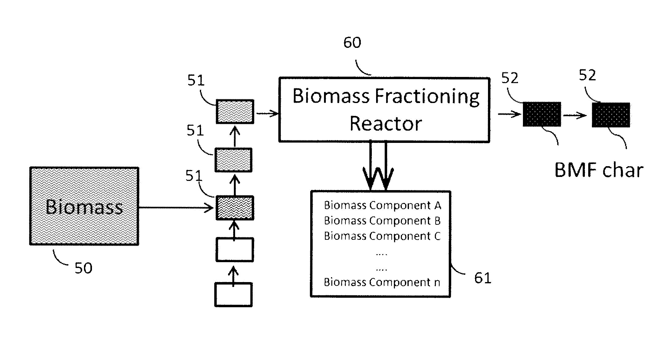
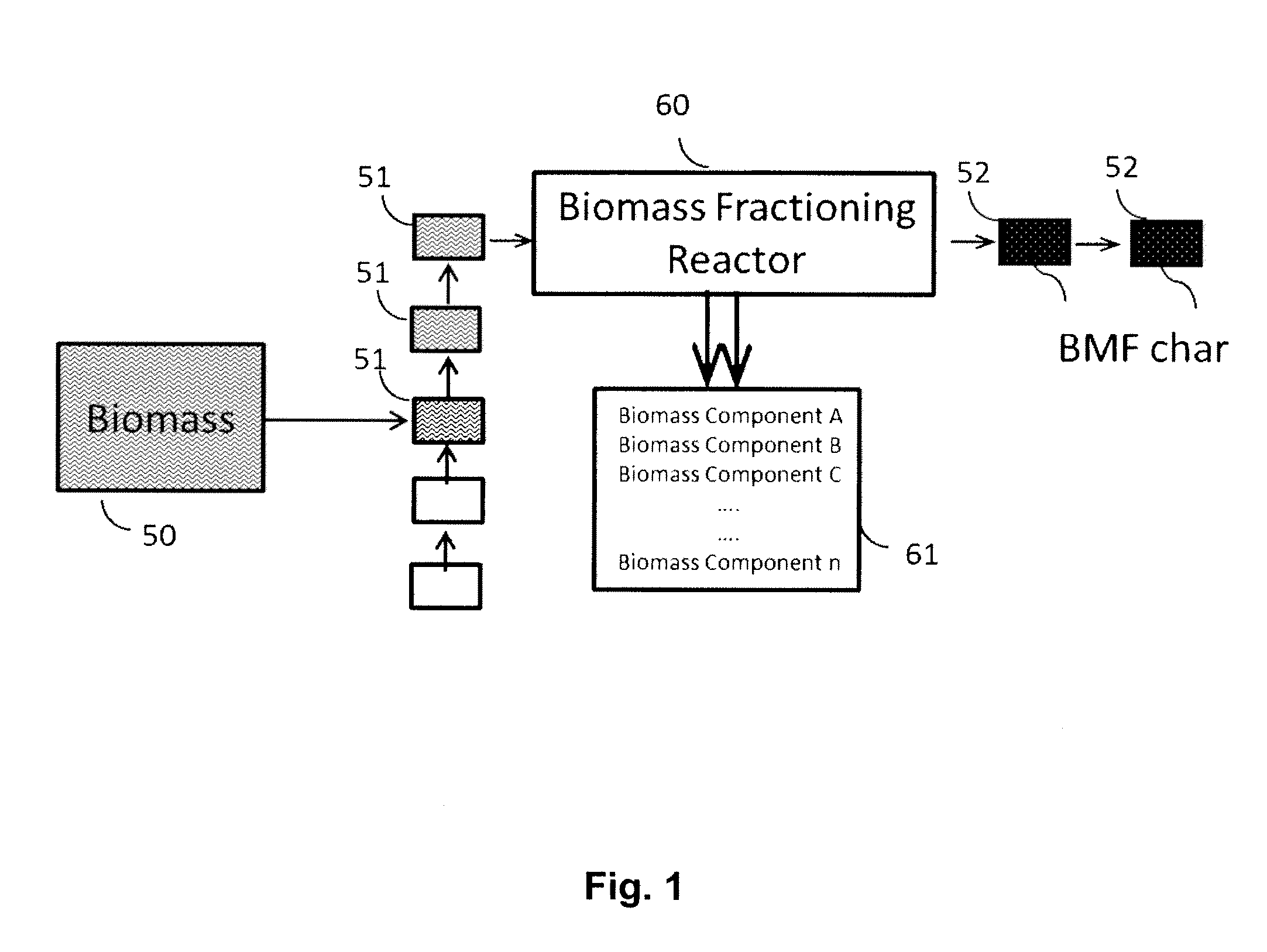
[0009]In various embodiments of the invention, biomass is subjected to sequential or concurrent temperature ramps and pressure shocks to produce useful volatile chemical compounds and a novel type of char (referred as BMF cha

Problems solved by technology

In the early 21st century, global warming and its interrelationship with the widespread use of fossil fuels has become one of the major technological challenges of our time.
At the low extreme, simple everyday cooking typically drives off water and starts to de-hydrolyze the biomass, causing the darkening and carmelization that we all associate with cooked foods.
Although some pyrolyzers are focused simply on producing syngas, there is considerable effort in the development of milder pyrolyzing conditions, which typically results in a condensed liquid commonly called bio-oil.
The fundamental problem with the resultant pyrolysis oil is that it is made up of hundreds to thousands of compounds, which are the result of subjecti

Method used


Image

  • Method for biomass fractioning by enhancing biomass thermal conductivity
  • Method for biomass fractioning by enhancing biomass thermal conductivity
  • Method for biomass fractioning by enhancing biomass thermal conductivity

Examples


example 1

[0043]Referring to FIGS. 5a and 5b, an exemplary embodiment of a system and method for biomass fractioning by enhancing biomass thermal conductivity will now be described. In FIG. 5a, a series of anvils 64 are contained in sealed reaction chamber 69 and driven by air cylinders having platen shafts 63. In the illustrated embodiment, there are two sets of anvils 64, wherein every other anvil 64 constitutes a set and moves in unison. The anvils 64 exert pressure shocks on biomass 61, which has been ground and spread out as a thin sheet on pallet 62. The biomass 61 within the latter pallet 62 can be heated to a predetermined temperature via heated anvils 64. The reaction chamber 69 includes an orifice 67 for the exit of generated volatile compounds, and an orifice 68 for the introduction of an inert carrier gas. Anvils 64 are heated alternately when they contact heater bar 66.

[0044]FIG. 5b is a 3-dimensional illustration of the anvil assembly 64 and heater bar 66. The biomass experience...

example 2

[0047]Referring to FIG. 7, another exemplary embodiment of a system and method for biomass fractioning by enhancing biomass thermal conductivity will now be described. In this implementation, each anvil 74 is directly heated via heat conducting electrical feedthroughs 80 attached to each anvil. Anvils 74 are again divided into two sets, each of which moves alternately to compact the biomass. The anvils 74 are heated by feedthroughs 80 to a predetermined temperature, determined by the volatilization temperature of the desired compounds. In the illustrated embodiment, one set of anvils 74 is driven by two pneumatically controlled shafts which move up and down within openings 75a, while another set of anvils 74 is driven by the center shaft (within center opening 75c).

[0048]FIG. 8a is an SEM image of BMF char obtained from corn after treatment using a system and method for biomass fractioning, as disclosed herein. FIG. 8b is a comparative SEM image of the same corn before treatment. It...


PUM

PropertyMeasurementUnit
Temperatureaaaaaaaaaa
Timeaaaaaaaaaa
Timeaaaaaaaaaa

Abstract

A method is disclosed for generating useful chemical intermediates from biomass using a novel pyrolysis reactor that utilizes the inherent thermal properties of carbon under compression as the biomass is subjected to sequential or concurrent temperature ramps. The ramps are sufficient to volatilize and selectively create different components, while the pressure application aids the selective decomposition of the biomass.

Description

TECHNICAL FIELD [0001]The present invention relates generally to systems for making renewable fuels, and more particularly to the conversion of biomass into useful volatile and non-volatile compounds via the use of inherent compressional features of carbon.DESCRIPTION OF THE RELATED ART [0002]In the early 21st century, global warming and its interrelationship with the widespread use of fossil fuels has become one of the major technological challenges of our time. Finding ways to more effectively use renewable biomass is a very important avenue for addressing these issues. Prior to the beginning of the industrial revolution, wood and plant oils were the primary source of energy for pre-industrial civilizations, which used this energy mainly for heating, cooking, and light. During this early period, biomass was simply burned in open air to produce heat and light. Several thousand years ago, mankind discovered that if the air supply was restricted during the burning process, a dense bl...

Claims


Application Information

Patent Timeline
IPC IPC(8): C01B3/02B01J19/00C07C1/00C07C53/00C07D307/02
CPCC10B47/12C10B53/02C10B57/02B02C21/00B01J6/008C10G2300/1014C10L1/04C10G1/02C10G2300/1011Y02E50/14Y02E50/32C10L1/02Y02E50/10Y02E50/30Y02P20/145Y02P30/20C10L5/447C10L2290/02C10L2290/06
Inventor CHEIKY, MICHAELSILLS, RONALD A.
Owner COOL PLANET ENERGY SYST
Why Eureka
Try Eureka