
Methods for Electrochemically Induced Cathodic Deposition of Crystalline Metal-Organic Frameworks

a metal-organic framework and electrochemical induced technology, applied in metal layered products, printing, electrical equipment, etc., can solve the problems of inefficiency of current methods, incompatible with many proposed applications, and difficult to grow mofs on surfaces to date, and achieve fast reaction times.

Inactive Publication Date: 2012-11-29
MASSACHUSETTS INST OF TECH
View PDF10 Cites 46 Cited by
  • Summary
  • Abstract
  • Description
  • Claims
  • Application Information

AI Technical Summary

Benefits of technology

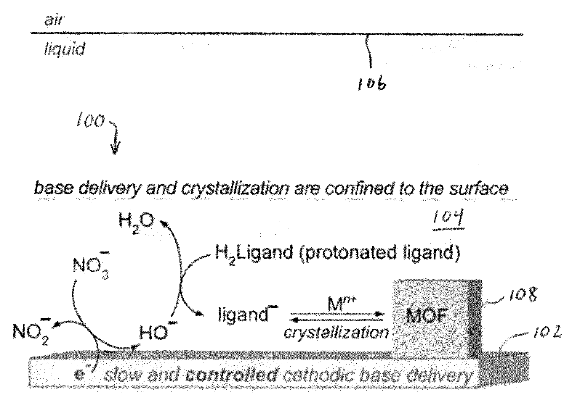
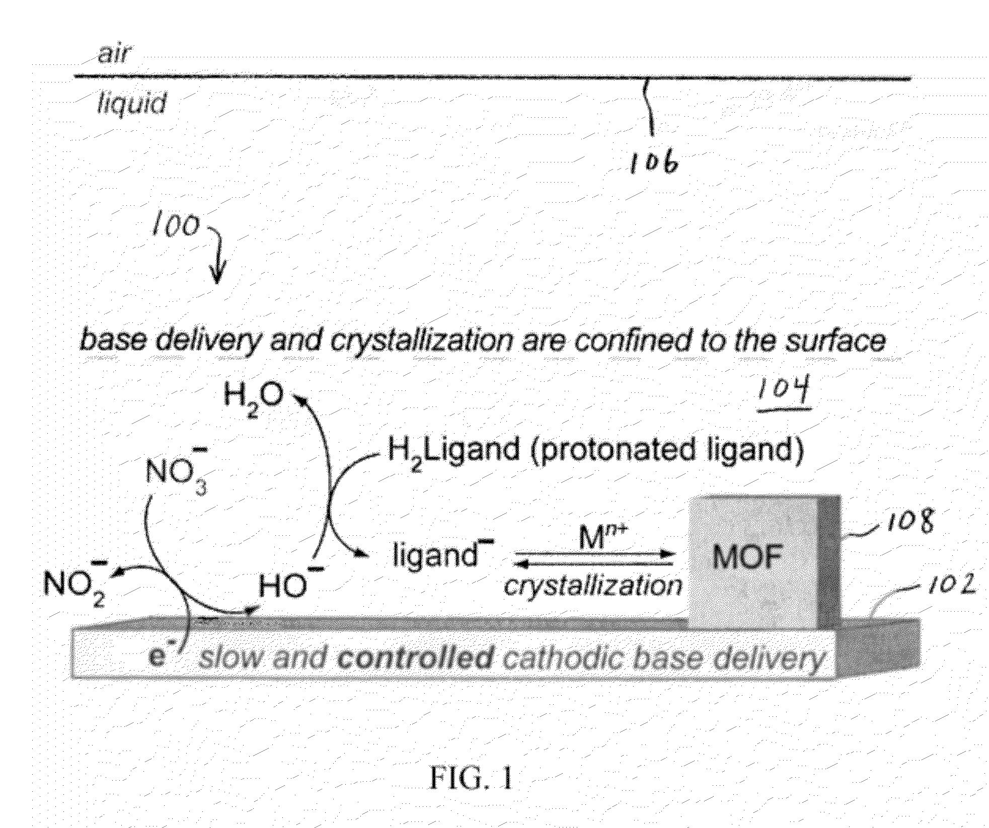
[0012]Electrochemically-induced cathodic deposition (also referred to herein as cathodic electrodeposition) of MOFs may be performed in a single step at room temperature—there is no need to maintain solvothermal conditions or perform multiple steps. Furthermore, unlike the anodic electrodeposition method discussed above, it is possible to use any of a wide variety of conductive surfaces and deposit MOFs composed of almost any metal ions and organic ligands thereon. The deposition surface need not provide a material for the MOF deposited thereon. Embodiments described herein allow crystallization in a single step with fast reaction times, wherein the reaction may be controlled, for example, by varying the current density and / or potential at the electroactive surface. Unlike the anodic electrodeposition method, the electroactive surface is not affected—it delivers electrons reductively and is not oxidized to deliver the metal ion that reacts to form the MOF. Any conductive surface can be used as the active cathode in embodiments described herein, and the methods are applicable to any metal ion in solution.

Problems solved by technology

However, current methods for producing MOFs are largely incompatible with many of the proposed applications.
Yet MOFs are solid, insoluble materials that are difficult to process, and it has been very challenging to grow MOFs on surfaces to date.
The method is inefficient because solvent wash between dipping steps is often necessary and excess solution is needed to ensure enough component will remain to react with the next dipping step.
For some MOFs, the approach is time-consuming because crystal growth may be slow.
This method is limited because the deposition surface is continually being corroded to supply one of the main starting materials in the MOF synthesis.
In addition, the metal contained in the MOF is limited to the type of metal electrode used as the anode (e.g., a Cu electrode can only give rise to Cu-based MOFs).

Method used


Image

  • Methods for Electrochemically Induced Cathodic Deposition of Crystalline Metal-Organic Frameworks
  • Methods for Electrochemically Induced Cathodic Deposition of Crystalline Metal-Organic Frameworks
  • Methods for Electrochemically Induced Cathodic Deposition of Crystalline Metal-Organic Frameworks

Examples


experimental examples

Example 1

[0068]A working electrolyte solution was produced by dissolving tetrabutylammonium hexafluorophosphate (TBAPF6, 1.94 g, 5.01 mmol, Sigma-Aldrich, 99.0% purity) in 50 mL of N,N-dimethylformamide (DMF) in a 100 mL Airfree® storage vessel. DMF was previously dried and deaerated through a solvent purification column. A quantity of 0.5 mL of water (Ricca, ASTM Type I, 18 MΩ cm resistivity) was subsequently added to the DMF solution to provide a 1% water content. Water is necessary for cathodic generation of hydroxide (see Table 1). The working electrolyte solution was deaerated once again using three consecutive freeze-pump-thaw cycles. The vessel was then brought into a nitrogen-filled glovebox. All further electrochemical experiments were performed inside the glovebox to avoid O2 contamination of the solution. O2 can get reduced itself, thus interfering with cathodic processes due to reduction. However, in an industrial setting, this step may not be necessary, because the reac...

example 2

[0073]Cathodic electrodeposition was used to synthesize Zn4O(NH2-BDC)3 (IRMOF-3). The procedure began by dissolving 45 mg of NH2-BDC (2-amino-1,4-benzenedicarboxylic acid) and 345 mg of Zn(NO3)2*4.5H2O in a 10 mL solution of 0.1M TBAPF6 (tetrabutylammoniumhexafluorophosphate) in DMF (N,N-dimethylformamide, dried and deaerated with argon) and 1% v / v water. The solution was shaken vigorously until dissolution and transferred to a two compartment glass H-cell equipped with a sintered glass filter. An FTO-covered glass working electrode was used, with a 1 cm2 platinum mesh counter electrode, and a Ag / Ag (cryptand) reference electrode. Approximately 1×1 cm2 of active electrode was exposed to solution. The cell was capped and purged with N2 for 30 minutes, before electrolyzing at −1.5 V for 15 minutes under a N2 blanket. Yellow-brown crystallites formed on the FTO surface along with metallic zinc. Referring to the X-ray diffraction results and predictions in FIG. 6, IRMOF-3 is isostructur...

example 3

[0074]Cathodic electrodeposition was used to synthesize [Et3NH]2[Zn3(BDC)4]*DMF. The process began by stirring 84 mg of H2BDC, 500 mg of Zn(NO3)2*8H2O, and 500 mg of Et3NHCl (triethylammonium chloride) in a 10 mL solution of 0.1 M TBAPF6 in dry and deaerated DMF solution. The stirring was performed under a nitrogen purge for 30 minutes inside a custom H-cell, containing a 1 cm2 Pt mesh working electrode, a 4 cm2 Pt mesh counter electrode, and a Ag / Ag (cryptand) reference electrode. A constant potential of −1.5 V was applied for 4 hrs. A gray solid layer was observed to form on the electrode after deposition. A small amount of Zn(BDC)*DMF was found to co-precipitate. X-ray diffraction results and predictions for the material produced during the experiment are presented in FIG. 7.


PUM

PropertyMeasurementUnit
Temperatureaaaaaaaaaa
Acidityaaaaaaaaaa

Abstract

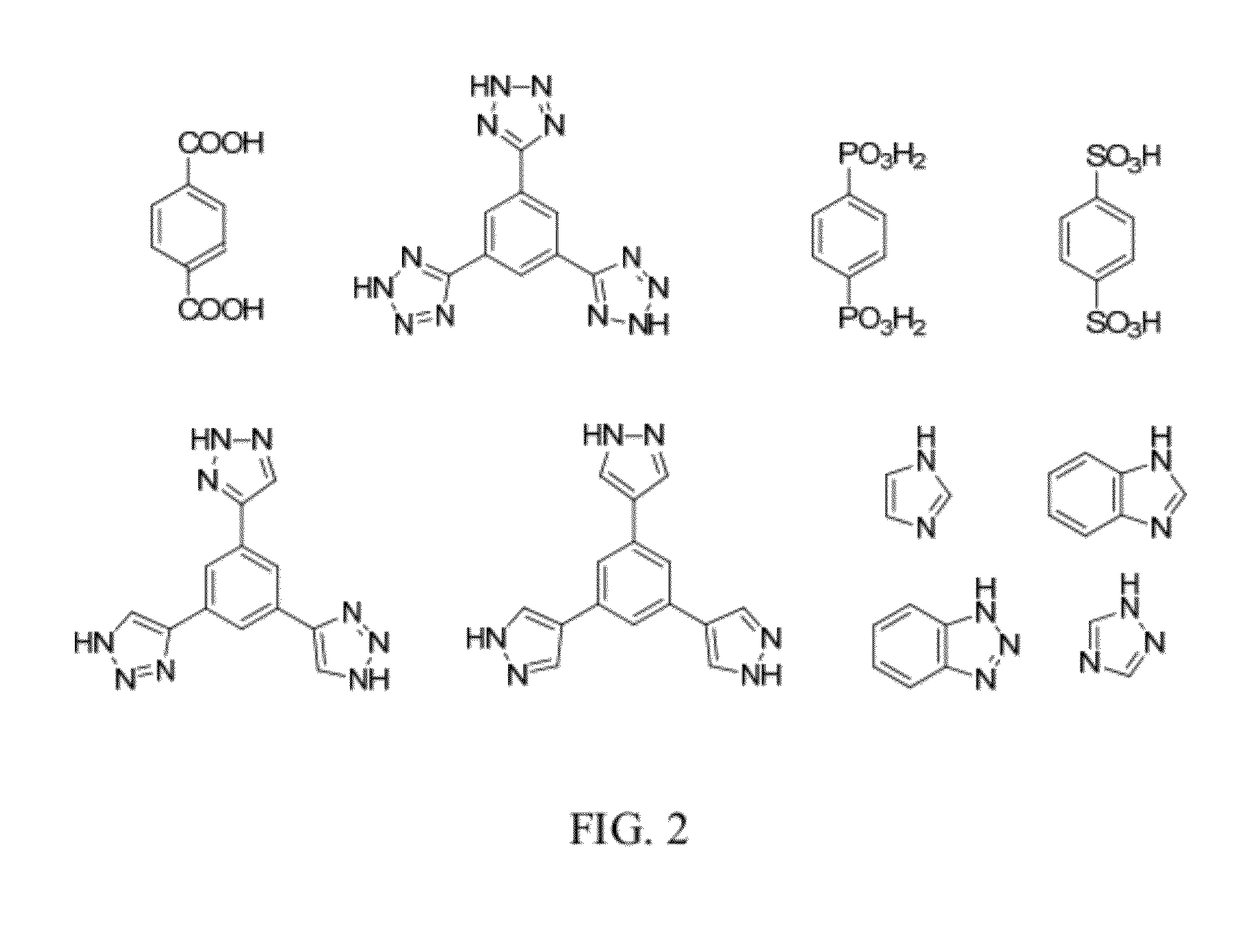
Embodiments of the invention relate to a method for preparing crystalline metal-organic frameworks (MOFs). The method includes the steps of providing an electrolyte solution in contact with a conductive surface, and applying a current or potential to the conductive surface in contact with the electrolyte solution. The electrolyte solution includes a protonated organic ligand, a metal ion, and a probase. Application of the reductive current or potential to the conductive surface produces the crystalline metal-organic framework (MOF) deposited on the conductive surface. The MOFs produced by the method may be incorporated into a gas separation membrane, a purification filter, and / or a sensor.

Description

CROSS-REFERENCE TO RELATED APPLICATION[0001]This application claims priority to and the benefit of, and incorporates herein by reference in its entirety, U.S. Provisional Patent Application No. 61 / 471,409, which was filed on Apr. 4, 2011.FIELD OF THE INVENTION[0002]This invention relates generally to methods for preparing metal-organic frameworks (MOFs). More particularly, in certain embodiments, the invention relates to electrochemical methods for synthesis, surface deposition, and growth of crystalline metal-organic frameworks.BACKGROUND OF THE INVENTION[0003]Metal-organic frameworks (MOFs) are crystalline microporous materials with very high surface areas and ordered regular monodisperse pores. MOF pores generally range from about 0.25 nm to about 2.5 nm in diameter and are within the micropore and small mesopore regime. Because of their high porosity, MOFs have utility as materials for gas storage, gas separation, drug transport, molecular separations, catalysis, and sensors. Ho...

Claims


Application Information

Patent Timeline
IPC IPC(8): C25D5/00B32B15/00C25D7/00B01D71/06B01D39/00
CPCB01D53/228B01J20/226C07C51/418C25D9/08C25D17/002B01J20/28033Y10T428/12674B01D71/028B01D71/02C07F3/003B01J20/30C07C63/28B01D71/0213
Inventor DINCA, MIRCEALI, MINYUAN
Owner MASSACHUSETTS INST OF TECH
Learn More