Electret condenser microphone

a condenser microphone and condenser technology, applied in the direction of loudspeakers, transducer types, microphone structural associations, etc., can solve the problems of very important cost considerations, and achieve the effect of low manufacturing cost and good dimensional stability

Active Publication Date: 2012-12-20
INVENSENSE
View PDF6 Cites 30 Cited by
  • Summary
  • Abstract
  • Description
  • Claims
  • Application Information

AI Technical Summary

Benefits of technology

[0018]The skilled person will understand that at least one of the carrier, the sidewall structure and the lid structure preferably comprises a single-layer or multi-layer printed circuit board. In certain embodiments, each of the carrier, the sidewall structure and the lid structure comprises a printed circuit board. The

Problems solved by technology

Miniature ECMs are sold in very large quantities for numerous highly cost-se

Method used


Image

  • Electret condenser microphone
  • Electret condenser microphone
  • Electret condenser microphone

Examples


first embodiment

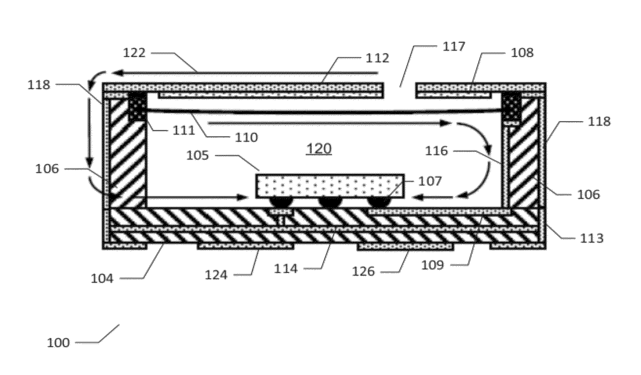
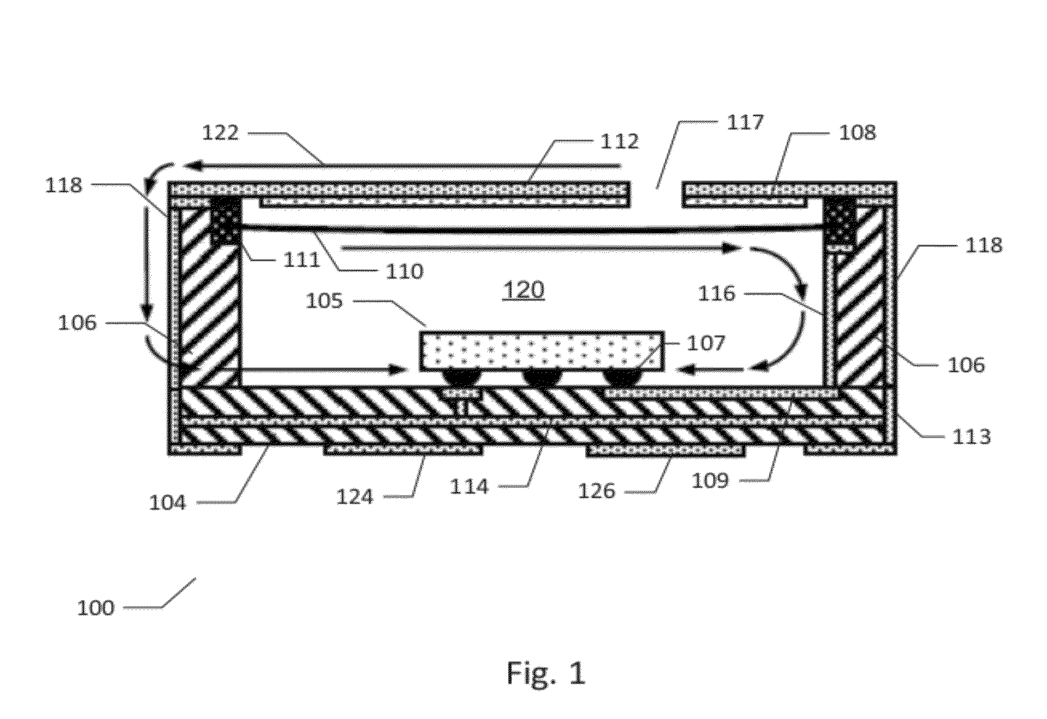
[0029]FIG. 1 is a vertical cross-sectional view of an electret condenser microphone (ECM) 100 according to the invention. The ECM 100 comprises a carrier 104 that may comprise a single layer or multi-layer printed circuit board or a ceramics substrate. The carrier 104 comprises first and second mutually insulated electrical traces or wires. The first electrical trace 109 is disposed on an upper surface of the carrier 104 also carrying or supporting a microphone preamplifier 105. A microphone preamplifier is provided on a semiconductor die or substrate 105. The microphone preamplifier may be integrated on an Application Specific Integrated Circuit (ASIC) fabricated in a sub-micron CMOS semiconductor process technology. The semiconductor die 105 is attached to the upper surface of the carrier 104 through a set of preamplifier pads or terminals which mate to a set of carrier pads A first preamplifier terminal 107 is an audio input of the microphone preamplifier 105 and the audio input ...

second embodiment

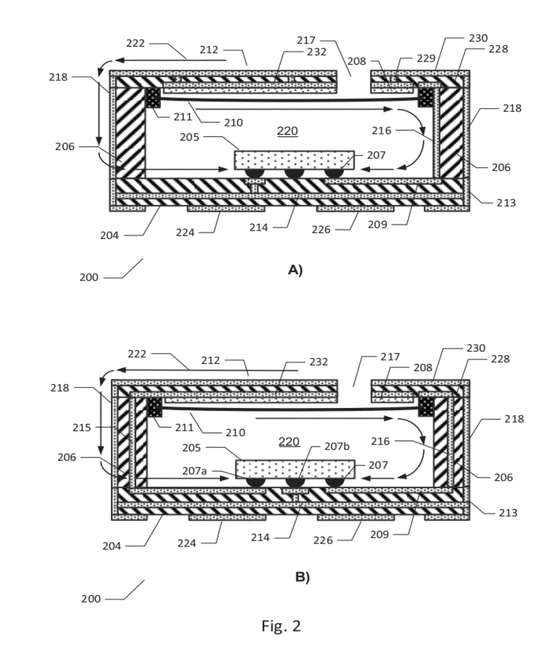
[0037]FIG. 3 is a schematic exploded view of the ECM 200 described above in accordance with the invention. The ECM housing is formed exclusively by three separate members, i.e. the carrier 204, the exterior sidewall structure 206 and the lid structure 212 which jointly form a substantially closed microphone housing. Furthermore, each of the carrier 204, the exterior sidewall structure 206 and the lid structure 212 is preferably fabricated in PCB material using conventional PCB manufacturing processes and technology to provide a low-cost housing structure. Furthermore, electrical wiring patterns provided on the outside surfaces of, or inside, the exterior sidewall structure 206 provide electrical interconnection between the conductive microphone diaphragm 210 (refer to FIG. 2) and the backplate structure, formed integrally with the lid structure 212, and the microphone preamplifier integrated on the ASIC 205. The adaptation of the exterior sidewall structure 206 to provide this type ...


PUM

PropertyMeasurementUnit
Lengthaaaaaaaaaa
Lengthaaaaaaaaaa
Electrical conductoraaaaaaaaaa

Abstract

The present invention relates to an electret condenser microphone which comprises an exterior sidewall structure attached to a carrier. The exterior sidewall structure comprises a non-conductive base material carrying first and second electrical wiring patterns electrically connected to first and second electrical traces, respectively, of the carrier. A diaphragm holder, carrying a conductive microphone diaphragm is attached to the sidewall structure to establish electrical connection between a conductive microphone diaphragm and one of the first and second electrical wiring patterns of the sidewall structure. A conductive perforated backplate is arranged in spaced relationship to the conductive microphone diaphragm. The conductive perforated backplate is electrically connected to another one of the first and second wiring patterns of the sidewall structure. The sidewall structure may therefore be utilized to provide electrical connectivity from the conductive microphone diaphragm and from the backplate to a microphone preamplifier arranged on the carrier.

Description

[0001]The present invention relates to an electret condenser microphone which comprisesan exterior sidewall structure attached to a carrier. The exterior sidewall structure comprises a non-conductive base material carrying first and second electrical wiring patterns electrically connected to first and second electrical traces, respectively, of the carrier. A diaphragm holder, carrying a conductive microphone diaphragm is attached to the sidewall structure to establish electrical connection between a conductive microphone diaphragm and one of the first and second electrical wiring patterns of the sidewall structure. A conductive perforated backplate is arranged in spaced relationship to the conductive microphone diaphragm. The conductive perforated backplate is electrically connected to another one of the first and second wiring patterns of the sidewall structure. The sidewall structure may therefore be utilized to provide electrical connectivity from the conductive microphone diaphr...

Claims


Application Information

Patent Timeline
IPC IPC(8): H04R19/01H04R31/00
CPCH04R1/04H04R19/016H04R2201/029Y10T29/49005B33Y80/00H01L2224/16225
Inventor LILLELUND, CHRISTIAN
Owner INVENSENSE
Why Eureka
Try Eureka