
Wind turbine blade with lightning protection system

a technology of lightning protection and wind turbine blade, which is applied in the direction of propellers, seating furniture, water-acting propulsive elements, etc., can solve the problems of increasing the risk of flashover, insufficient protection of the layer of insufficient influence of the layer on the electric field around the lightning down conductor, so as to prevent the build-up of streamers and/or leaders, prevent the effect of lightning strikes

Active Publication Date: 2012-12-20
LM GLASSFIBER
View PDF3 Cites 15 Cited by
  • Summary
  • Abstract
  • Description
  • Claims
  • Application Information

AI Technical Summary

Benefits of technology

[0017]The arrangement of the down conductor provided with the first conductive layer having a relative low conductivity helps to prevent the build-up of streamers and / or leaders. The electrical field around the inner conductor is lowered during a lightning strike by acting as a parasitic conductor. This minimises the problem with vertical streamers, which is especially present in connection with positive lightning strikes, which normally account for about 10% of lightning strikes. Such streamers and leaders are pre-stages of lightning strikes and thus, preventing their build-up also prevents lightning strikes. Moreover, the necessity of multi-receptors may be avoided. If the resistance of the conductive layer is too small, which is the case for the embodiments shown in for instance WO 2006 / 099880, the conductive layer may act as a lightning receptor and increasing the risk of a flashover, potentially damaging the insulation of the lightning down conductor and the wind turbine blade. On the other hand, if the sheet resistance is too large, the influence of the layer on the electric field around the lightning down conductor is insufficient to provide the needed protection. It has surprisingly found that the addition of the first conductive layers having a relative low conductivity provides a much improved, efficient protection against positive lightning strikes compared to conventional lightning protection systems and down conductors.
[0018]At its root end, the lightning down conductor is preferably connected to earth via the rotor hub so that current from a lightning strike is safely conducted from the lightning receptor to the lightning down conductor and finally to earth. However, it may be sufficient with a spark gap between the lightning down conductor and the rotor hub.
[0021]According to a preferred embodiment, the shell body is made of a composite material, such as a fibre-reinforced polymer material. Advantageously, the shell body is made of an electrically non-conductive material. Thus, the reinforcement fibres are preferably not made of a metal or carbon. According to a particular advantageous embodiment, the reinforcement fibres are glass fibres. The polymer material may for instance be epoxy, polyester or vinyl ester. Thus, the shell body is in itself electrically non-conductive, thus minimising the risk of a lightning strike hitting the wind turbine blade and further minimising the risk of a flashover to the shell body.
[0028]Advantageously, the at least one lightning receptor is arranged at or in the immediate vicinity of the tip of the blade. Thereby, the lightning receptor will be located at a high position, when the wind turbine blade is pointing upwards, thus maximizing the probability of a lightning strike hitting the lightning receptor instead of another part of the blade. However, in principle the down conductor according to the invention may also be combined with a multi-receptor solution, where a plurality of lightning receptors are used, and one or more lightning down conductors are used.

Problems solved by technology

If the resistance of the conductive layer is too small, which is the case for the embodiments shown in for instance WO 2006 / 099880, the conductive layer may act as a lightning receptor and increasing the risk of a flashover, potentially damaging the insulation of the lightning down conductor and the wind turbine blade.
On the other hand, if the sheet resistance is too large, the influence of the layer on the electric field around the lightning down conductor is insufficient to provide the needed protection.

Method used


Image

  • Wind turbine blade with lightning protection system
  • Wind turbine blade with lightning protection system
  • Wind turbine blade with lightning protection system

Examples


Embodiment Construction

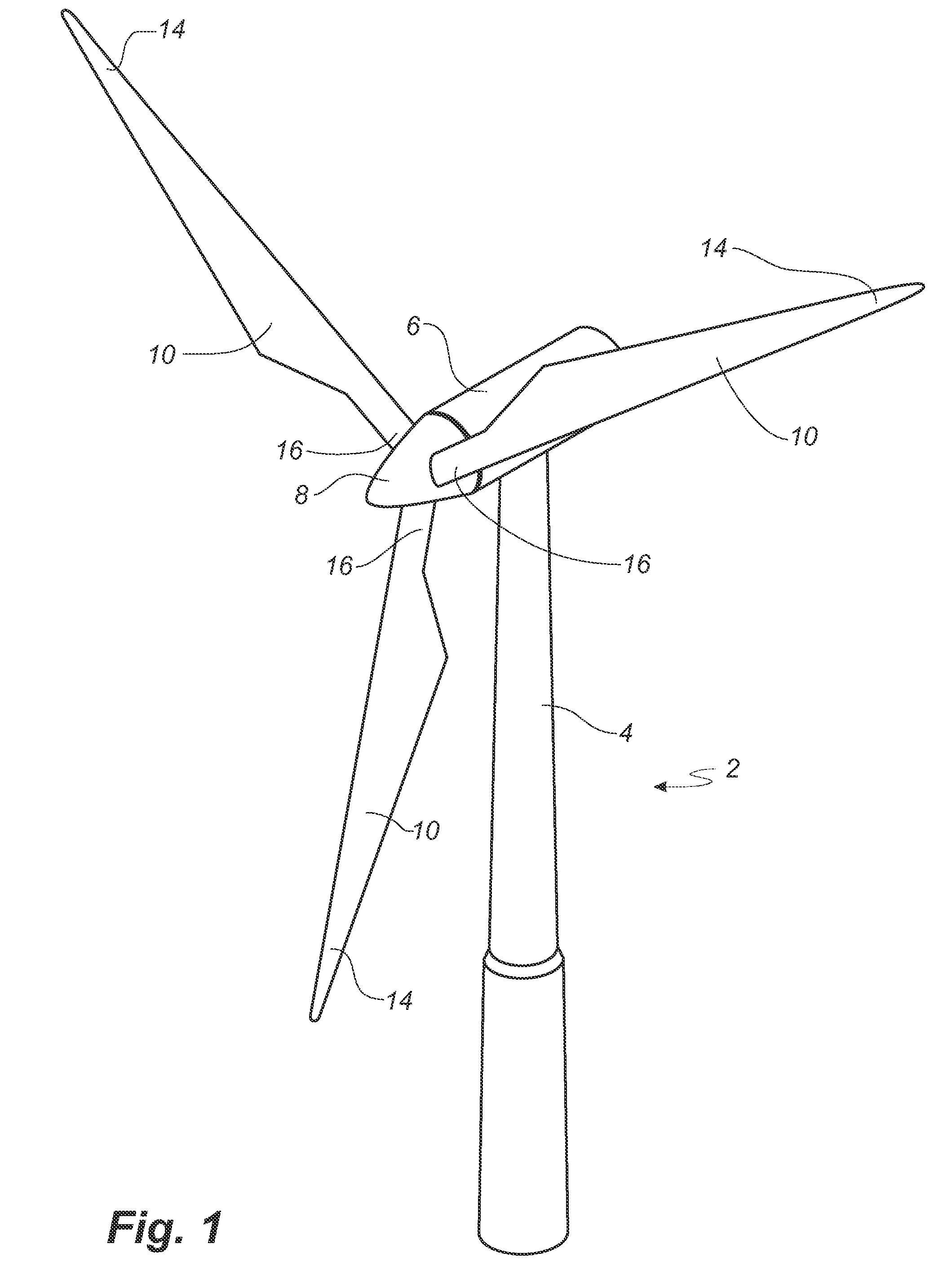
[0039]FIG. 1 illustrates a conventional modern upwind wind turbine according to the so-called “Danish concept” with a tower 4, a nacelle 6 and a rotor with a substantially horizontal rotor shaft. The rotor includes a hub 8 and three blades 10 extending radially from the hub 8, each having a blade root 16 nearest the hub and a blade tip 14 furthest from the hub 8.

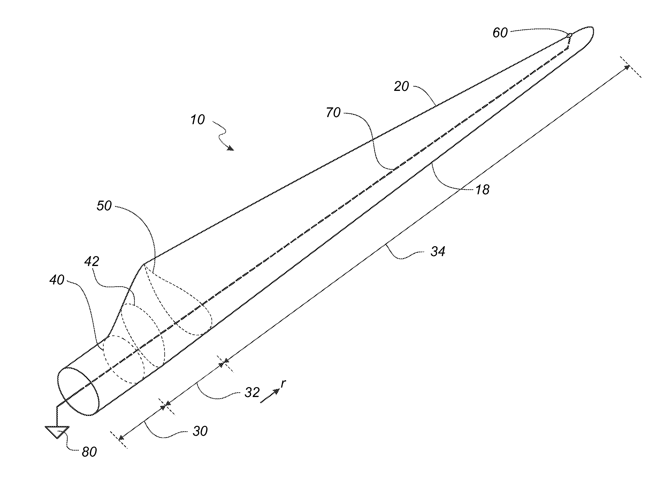
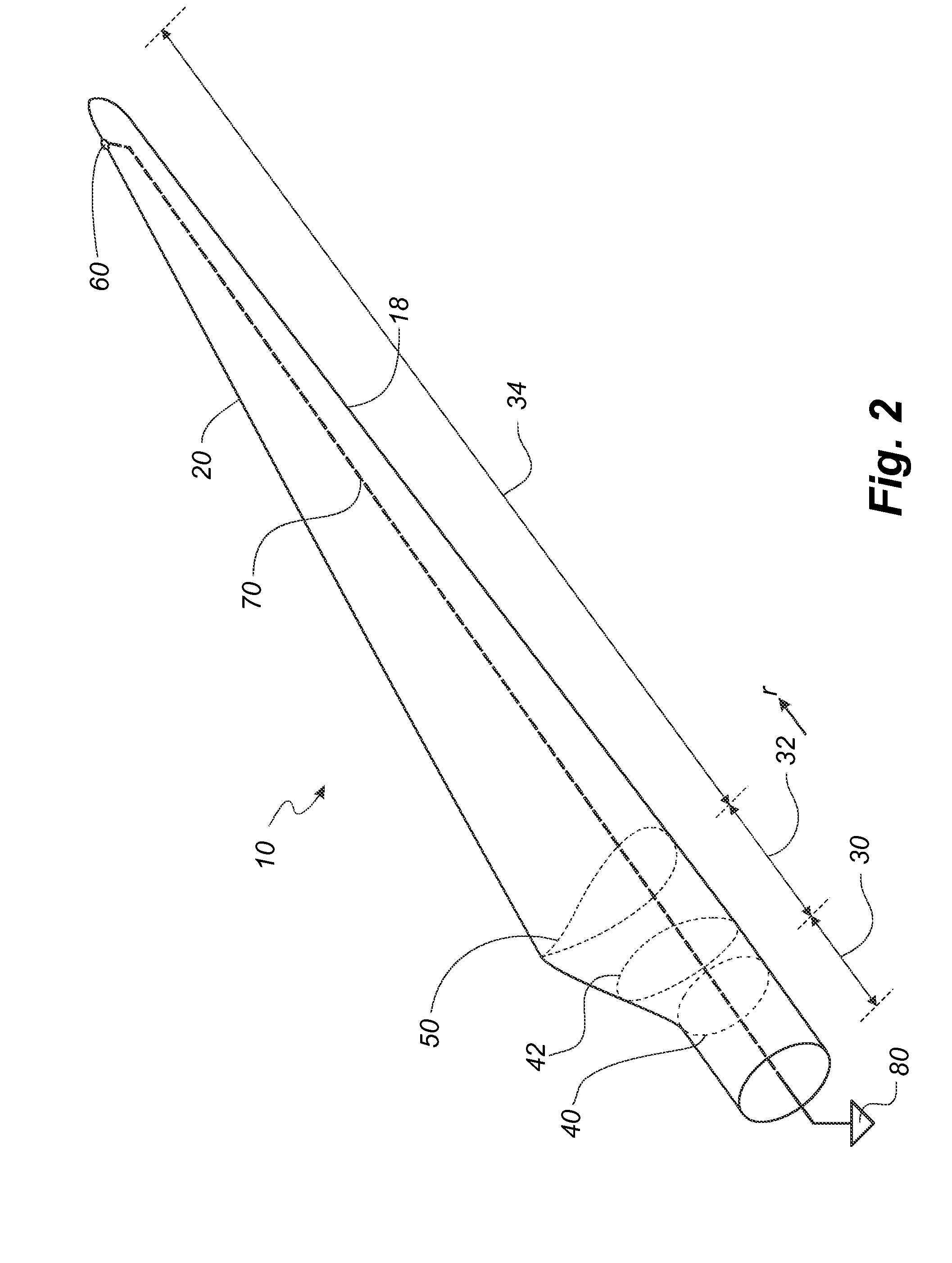
[0040]FIG. 2 shows a schematic view of a first embodiment of a wind turbine blade 10 according to the invention. The wind turbine blade 10 has the shape of a conventional wind turbine blade and comprises a root region 30 closest to the hub, a profiled or an airfoil region 34 furthest away from the hub and a transition region 32 between the root region 30 and the airfoil region 34. The blade 10 comprises a leading edge 18 facing the direction of rotation of the blade 10, when the blade is mounted on the hub, and a trailing edge 20 facing the opposite direction of the leading edge 18.

[0041]The airfoil region 34 (also called th...


PUM


Abstract

A wind turbine blade with a lightning protection for a blade with a shell body has at least one lightning receptor arranged freely accessible in or on a surface of the shell body surface, and a lightning down conductor electrically connected to the lightning receptor and comprising an inner conductor made of electrically conductive material imbedded in a bedding insulation made of an electrically non-conductive material. The lightning down conductor further includes a first conductive layer having a resistance in the range of 10 to 10,000 Mega Ohm per meter (MΩ / m). The first conductive layer is located in a transverse distance from the inner conductor and being electrically isolated from the inner conductor.

Description

Technical Field[0001]The present invention relates to a wind turbine blade with a lightning protection system, wherein the blade comprises a shell body and comprises a longitudinal direction with a root end and a tip end, the blade further comprising a profiled contour including a pressure side and a suction side, as well as a leading edge and a trailing edge with a chord having a chord length extending there between, the profiled contour, when being impacted by an incident airflow, generating a lift. The lightning protection system comprises: at least one lightning receptor arranged freely accessible in or on a surface of the shell body surface, and a lightning down conductor electrically connected to the lightning receptor and comprising an inner conductor made of electrically conductive material imbedded in a bedding insulation made of an electrically non-conductive material. The invention also relates to a wind turbine comprising such wind turbine blades.BACKGROUND[0002]It is kn...

Claims


Application Information

Patent Timeline
Patent Type & Authority Applications(United States)
IPC IPC(8): F03D11/00F03D1/06
CPCF03D11/0033F03D80/30Y02E10/721Y02E10/722Y02E10/72
Inventor HANSEN, LARS BO
Owner LM GLASSFIBER
Learn More