Composite coatings for oxidation protection

Inactive Publication Date: 2013-01-03
NAT RES COUNCIL OF CANADA
View PDF3 Cites 17 Cited by
  • Summary
  • Abstract
  • Description
  • Claims
  • Application Information

AI Technical Summary

Benefits of technology

[0009]Composite electrodeposited coatings are provided which enable the practical use of chromia forming alloys as solid oxide fuel cell interconnect substrate materials at elevat

Problems solved by technology

However, such alloys suffer from poor oxidation behaviour, oxide scal

Method used


Image

  • Composite coatings for oxidation protection
  • Composite coatings for oxidation protection
  • Composite coatings for oxidation protection

Examples


example 1

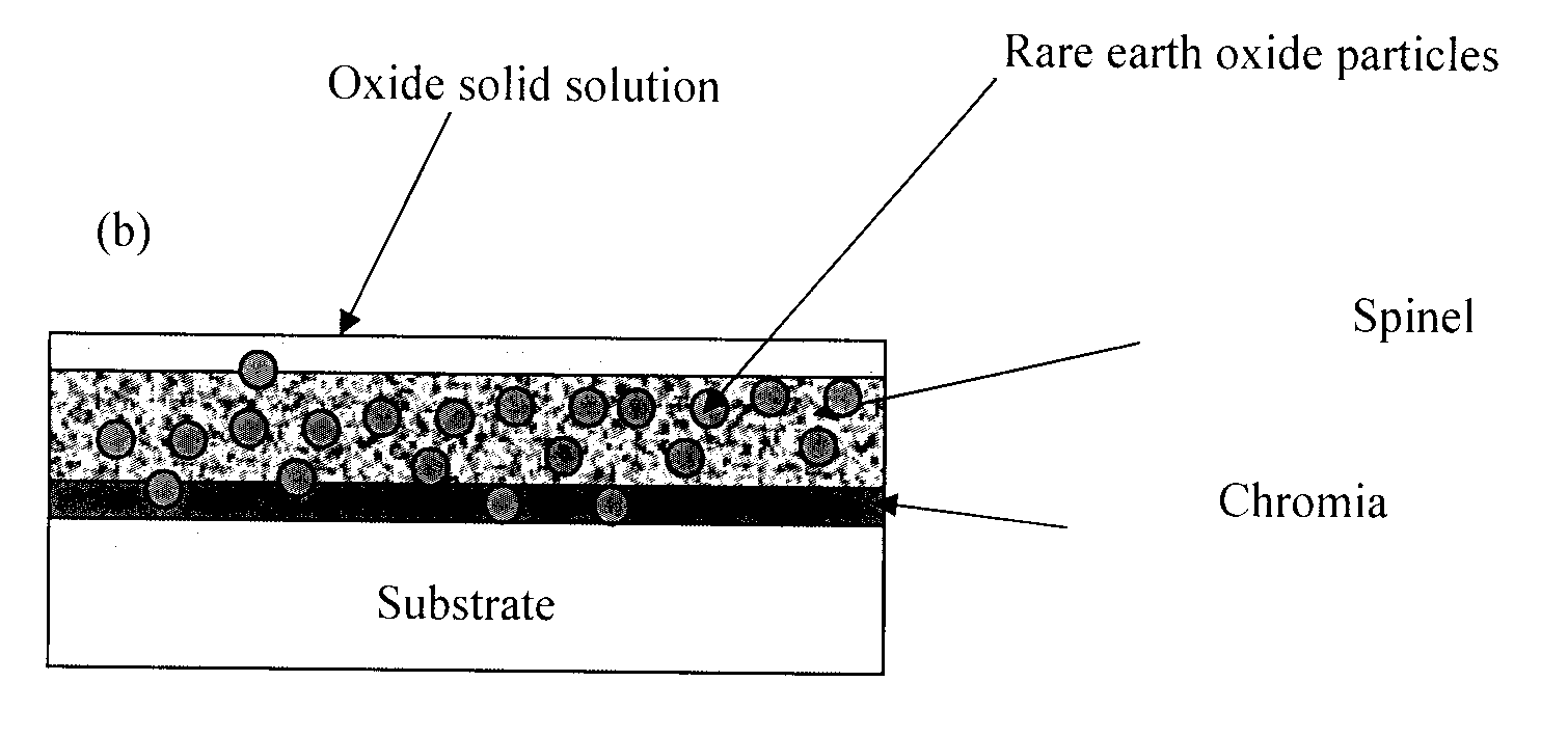
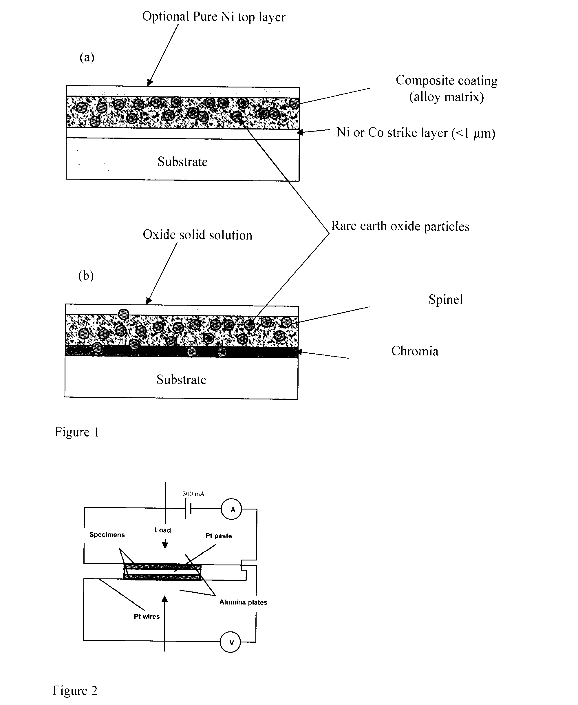
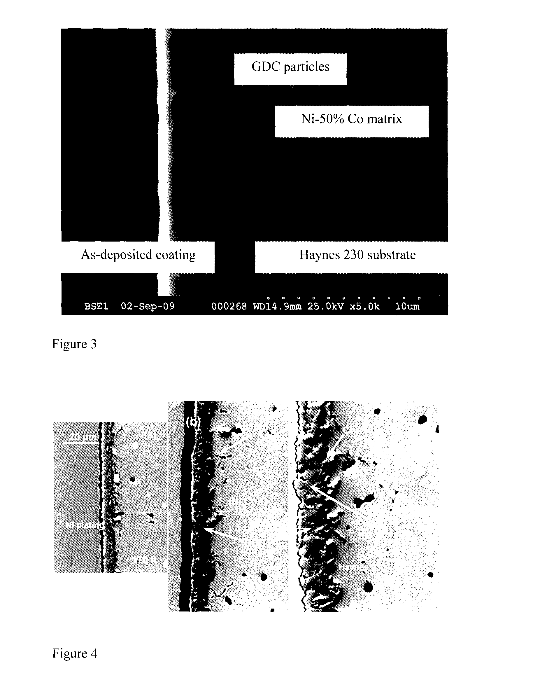
[0048]FIG. 1 represents a schematic drawing of as deposited coating (FIG. 1a) and of oxidized coating (FIG. 1b) with corresponding different layers. Haynes® 230®, Ni-based superalloy the composition of which is listed in Table I, was selected as the cathode substrate. The coating comprises Ni and Co alloy (50% Co) and gadolinia doped ceria, (CeO2)0.9—(Gd2O3)0.3(GDC) particles (d10=0.4 μm, d50=0.5 μm, d95=1 μm). Electroplating was used for deposition of the composite coating. The planar anode and cathode substrate were placed horizontally in the plating bath. The composition and operating conditions of bath used for composite electrodeposition are listed in Table II.

TABLE Idescribes the nominal compositions of Haynes ® 230 ® (wt %)NiCrWMoFeCoMnSiAlCLaB5722142350.50.40.30.10.020.015

[0049]The cathode substrate is formed from a 2 mm thick Haynes® 230® sheet, cut into 20×20 mm coupons. The coupons were ground by grit 600 abrasive paper and cleaned ultrasonically in an alkaline cleaning s...

example 2

[0062]The procedure described in Example 1 was used to coat ZMG232L, ferritic stainless steel (Hitachi product). The coating composition is also the same as in Example 1. The composition for ZMG232L is listed in Table IV. The measurement and characterization techniques were identical to Example 1. The oxidation weight gain profiles in FIG. 15 show significant reduction in oxidation weight gain for NiCo / GDC composited coated specimens. The oxidation weight gain for coated specimens without GDC particles is much higher than even uncoated substrate. This indicates that rare earth metal oxide particles are indispensible constituent of the coating.

[0063]As seen in FIG. 16, the ASR values at different temperatures for NiCo / GDC (50% Co) coated ZMG232L® are well below the generally accepted criteria for SOFC interconnects that is 100 mΩcm2.

TABLE IVnominal composition (wt. %) of ZMG232L ® ferriticstainless steelFeCrCSiMnNiAlZrLaBal.220.020.080.460.340.050.190.05

example 3

[0064]Interconnect plates of Crofer® 22H (see Table V for composition) were coated using the same coating composition and technique described in Example 1. Short stack cell testing was performed for 800 hours at 700° C. and is intended to be continued for several thousand hours. The coated interconnect plates showed 0.1-0.2% / 1000 hours less degradation than uncoated plates. However, longer times are required to observe the full benefits of the coating since chromium poisoning effect requires several thousand of hours to appear.

TABLE Vnominal composition (wt %) of Crofer 22 H ® ferritic stainless steelFeCrCNSSiMnAlWTiLaPCuBal.20-240.03 max0.03 max0.006 max0.1-0.60.3-0.80.1 max1-30.02-0.20.04-0.20.05 max0.5 max


PUM

PropertyMeasurementUnit
Temperatureaaaaaaaaaa
Lengthaaaaaaaaaa
Lengthaaaaaaaaaa

Abstract

The invention disclosed relates to an oxidized metal matrix composite coated substrate, comprising a substrate made of a material selected from the group consisting of a chromia-forming Fe, Ni and/or Co based alloy containing an amount of Cr ranging from 16 to 30 wt %, and an oxide-dispersion strengthened Cr-based alloy and a plain Cr-based alloy, and an oxidized metal matrix composite coating comprising at least two metals and reactive element oxide particles in the form of a tri-layer scale on the substrate surface comprising an inner chromia layer, an intermediate layer of a spinel solid solution formed by Cr and one or more of the deposited metals selected from the group consisting of Ni, Co, Cu, Mn, Fe and Zn and a mixture thereof, and an electrically conductive top layer comprising oxides of one or more deposited metals selected from the group consisting of Ni, Co, Cu, Fe, Mn, Zn and a mixture thereof, which is substantially free from Cr ions, and wherein one or more of such layers contain particles of doped or undoped oxides of a rare earth metal selected from the group consisting of Ce, Y, La, Hf, Zr, Gd and a mixture thereof.

Description

BACKGROUND OF THE INVENTION[0001]The invention disclosed relates to composite oxide coatings, and hi particular to an oxidized metal-matrix composite coated substrate and a method of coating therefore, wherein the coated substrate may be used as an electrical interconnect device for use at high temperature for oxidation protection, and specifically in solid oxide fuel cells (SOFC).[0002]Several different types of fuel cells are under development, including the solid oxide fuel cell (SOFC). Solid oxide fuel cells typically operate at temperatures in the range of 600-1000° C. The individual cells are electrically connected in series to one another by a device known as an electrical interconnect, to form a multi-cell stack unit producing acceptable voltage. The interconnect material must be physically and chemically stable and electronically conductive under high-temperature oxidizing operating conditions of the fuel cell.[0003]Recently, chromia forming alloys have been considered as t...

Claims


Application Information

Patent Timeline
IPC IPC(8): C25D11/38H01M2/22B32B15/04H01M50/528
CPCC23C8/02C25D15/00C25D5/50C25D5/12
Inventor SHAIGAN, NIMAQU, WEI
Owner NAT RES COUNCIL OF CANADA
Why Eureka
Try Eureka