
Laminated body comprising porous layer and functional laminate using same

a technology of functional laminates and porous layers, which is applied in the field of laminates, can solve the problems of large molecular weight of polymeric compounds, inability to use, and inability to solve phase transition techniques such as variations in film qualities, and achieve excellent flexibility, sufficient strength, and excellent printability

Inactive Publication Date: 2013-01-24
DAICEL CHEM IND LTD
View PDF15 Cites 30 Cited by
  • Summary
  • Abstract
  • Description
  • Claims
  • Application Information

AI Technical Summary

Benefits of technology

The present invention is a layered body with a porous layer that is excellent in flexibility and provides superior strength and folding endurance. The porous layer is supported by a base and contains a polymer with a crosslinkable functional group that can be crosslinked to form a crosslinked structure. The crosslinked structure improves adhesion between the substrate and the porous layer and increases rigidity, heat resistance, chemical resistances, and endurance. The layered body with a porous layer can be used in various fields such as low-permittivity material, separator, cushion material, and ink-image receiving sheet. The layered body also provides good printability and can be used for various functional materials such as electromagnetic wave controlling material, circuit substrate, antenna, heat radiating plate, and some others. The functional laminate, which includes the layered body with a porous layer and a functional layer, exhibits excellent adhesion, film strength, heat resistance, chemical resistances, and endurance.

Problems solved by technology

Thus, the technique has a problem that the resin (polymeric compound), which is to constitute the porous layer, is limited to a resin soluble in a good solvent having a low boiling point, so that a polymeric compound large in molecular weight, which is essentially slightly soluble, cannot be used.
A painting solution low in viscosity is preferably used in order that the polymeric compound can be dissolved therein and further a solvent therein can be rapidly vaporized after the formation of the painted film; as a result, however, the following inconveniences are caused: this painted film cannot easily have a sufficient thickness; out of constituting components of the painted film, components that are not removed when the solvent is vaporized remain in the porous layer, so that a nonvolatile additive is not easily usable; and the structure of the yielded porous layer depends largely on heating conditions and production environmental conditions in the production process, so that the porous layer is not stably produced with ease, thereby resulting in a tendency that porous layers produced by the technique are varied in qualities, such as pore diameter, rate of open area, porosity, and thickness.
According to the phase transition technique disclosed in WO98 / 25997, production environmental conditions can be stabilized; however, the above-mentioned problems in the dry phase transition technique, such as a variation in film qualities, cannot be solved since the technique basically makes use of a heating and drying manner.
In the case of considering the usage of the layered body disclosed in WO98 / 25997, the inventor's investigations have made the following evident: in the case of bonding a copper foil piece onto the layered body to prepare a copper clad layered plate, and then etching the plate to form a circuit pattern, it is feared that a sufficient bonding strength can not be exhibited between the copper foil piece and the layered body since the porous layer is weak in strength.
When the layered body disclosed in WO98 / 25997 is used as a cushion material, the film thickness of the layered body is not easily made large since the layered body is formed by use of a low-viscosity painting solution.
Thus, it is difficult to cause the layered body to exhibit sufficient cushion performance.

Method used


Image

  • Laminated body comprising porous layer and functional laminate using same
  • Laminated body comprising porous layer and functional laminate using same
  • Laminated body comprising porous layer and functional laminate using same

Examples


example 1

Porous Layer Layered Body A

[0307]The following were mixed with each other: a polyamideimide resin solution (trade name: “VYLOMAX N-100H” manufactured by Toyobo Co., Ltd.; solid content concentration: 20% by weight; solvent: NMP (N-methyl-2-pyrrolidone); solution viscosity: 350 dPa·s / 25° C.); a novolak type epoxy resin (trade name: “YDCN-700-5”, manufactured by Tohto Kasei Co., Ltd.) as a crosslinking agent; and NMP as a solvent. The blend ratio of the polyamideimide resin / NMP / the novolak type epoxy resin was a ratio by weight of 15 / 85 / 5. In this way, a film-forming material solution was obtained. A polyimide film (trade name: “KAPTON 200H” manufactured by Du Pont-Toray Co., Ltd.; thickness: 50 μm) as a base was fixed on a glass plate with a tape. A film applicator was used to cast the material solution, the temperature of which was set to 25° C., thereon under a condition that the gap between the film applicator and the base was 51 μm. After the casting, the workpiece was rapidly pu...

example 2

Porous Layer Layered Body B

[0309]A layered body B wherein a porous layer was layered on a base was yielded by making the same operations as in Example 1 except that a film-forming material solution was yielded by mixing the polyamideimide resin, NMP and the novolak type epoxy resin with each other to set the ratio by weight of the polyamideimide resin / NMP / the novolak type epoxy resin to 15 / 85 / 10. The thickness of the resultant porous layer was about 11 μm, and the total thickness of the layered body was about 61 μm.

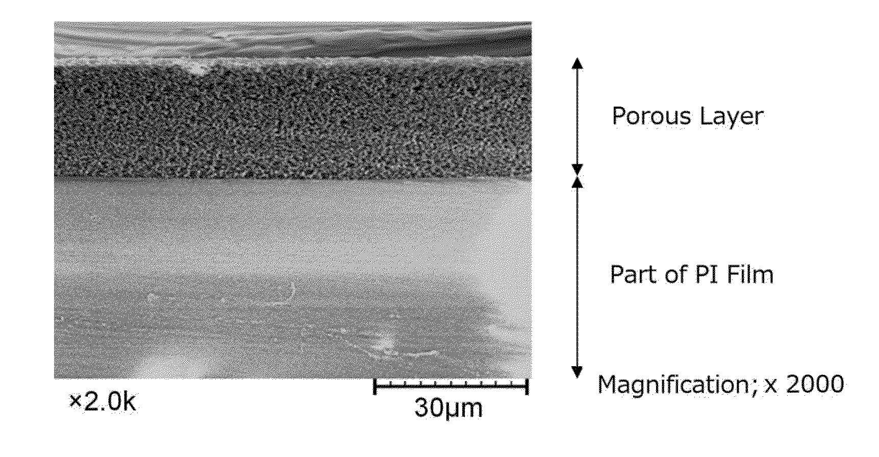
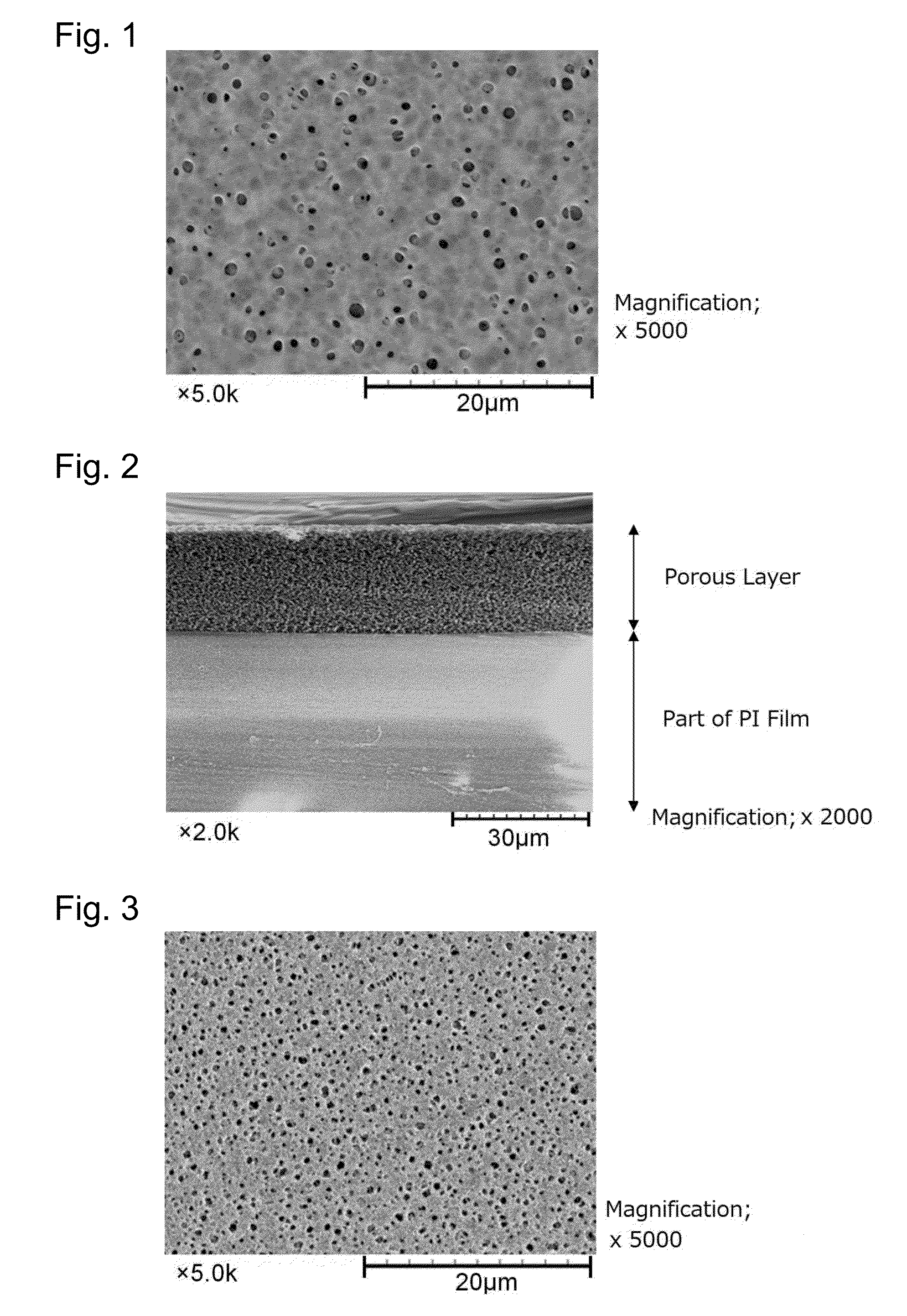
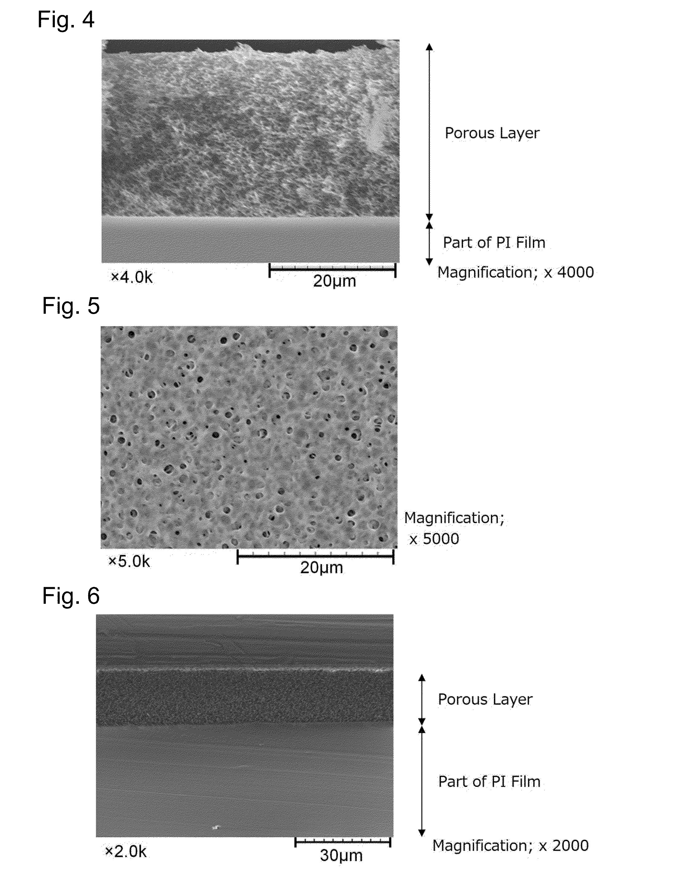
[0310]About the resultant layered body B, a tape peeling test was made. As a result, no interfacial peeling was caused between the base and the porous layer. This layered body B was observed through an electron microscope. As a result, the porous layer adhered closely to the polyimide film, and recognized was a tendency that a skin layer was basically formed on the surface of the porous layer. Throughout the inside of the porous layer, there were independent and substanti...

example 3

Porous Layer Layered Body C

[0311]A layered body C wherein a porous layer was layered on a base was yielded by making the same operations as in Example 1 except that a film-forming material solution was yielded by mixing the polyamideimide resin, NMP and the novolak type epoxy resin with each other to set the ratio by weight of the polyamideimide resin / NMP / the novolak type epoxy resin to 15 / 85 / 15. The thickness of the resultant porous layer was about 21 μm, and the total thickness of the layered body was about 71 μm.

[0312]About the resultant layered body C, a tape peeling test was made. As a result, no interfacial peeling was caused between the base and the porous layer. This layered body C was observed through an electron microscope. As a result, the porous layer adhered closely to the polyimide film, and recognized was a tendency that a skin layer was basically formed on the surface of the porous layer. Throughout the inside of the porous layer, there were independent and substanti...


PUM

PropertyMeasurementUnit
porosityaaaaaaaaaa
pore diameteraaaaaaaaaa
thicknessaaaaaaaaaa

Abstract

A layered body which includes a porous layer. The layered body having improved properties, such as adhesion between its substrate and its porous layer by the formation of a crosslinked structure; a functional laminate using the porous layer layered body; and a production processes thereof. The layered body includes a base and the porous layer on at least one surface of the base. The base is a resin film made of at least one resin material of polyimide resins, polyamideimide resins, polyamide resins, and polyetherimide resins, or is a metal foil piece, and the porous layer is made of a composition containing at least one polymer of polyimide resins, polyamideimide resins, polyamide resins, and polyetherimide resins as a main component, and a crosslinking agent. Additionally, the porous layer has fine pores having an average pore diameter of 0.01 to 10 μm, and a porosity of 30 to 85%.

Description

TECHNICAL FIELD[0001]The present invention relates to a layered body having, on its base, a porous layer made mainly of a polymer, a process for producing the layered body, a functional laminate using the layered body having the porous layer, and a process for producing the laminate.[0002]The layered body with a porous layer of the present invention makes good use of the pore properties of the porous layer, thereby being used as a substrate material in a wide range of fields of a low-permittivity material, a separator, a cushion material, an ink-image receiving sheet, an electrically insulating material, a heat insulating material, and others. Furthermore, when a surface of the porous layer is functionalized, the layered body can be used as a substrate for a circuit, a heat radiating material (such as a heat sink or a heat radiating plate), an electromagnetic wave controlling material such as an electromagnetic wave shield or an electromagnetic wave absorbent, an antenna, a cell cul...

Claims


Application Information

Patent Timeline
Patent Type & Authority Applications(United States)
IPC IPC(8): B32B3/26H05K1/03B05D3/00B05D5/12B32B27/08B32B15/08C08J7/043C08J7/044C08J7/046C08J7/056
CPCB32B5/00B32B5/18B32B2307/20B32B27/34B32B27/281C08J2379/08C08J2479/08Y10T428/249988Y10T428/249991Y10T428/24999C08J7/0427C08J7/043C08J7/046C08J7/044C08J7/056B32B15/08C08J9/28
Inventor YAMATO, YO
Owner DAICEL CHEM IND LTD
Learn More