Durable fine wire lead for therapeutic electrostimulation and sensing

a wire lead and sensing technology, applied in the field of wire wire lead electrostimulation and sensing devices, can solve the problems of failure, high pressure, failure, etc., and achieve the effects of small diameter, low mass, and increased flexibility

Inactive Publication Date: 2013-02-14
CARDIA ACCESS
View PDF2 Cites 35 Cited by
  • Summary
  • Abstract
  • Description
  • Claims
  • Application Information

AI Technical Summary

Benefits of technology

[0020]Alternative methods of producing fiber coax include drawing a core fiber, coating that core with a metal buffer and drawing additional silica or glass over the assembly and cladding that final assembly with an additional metal buffer. Fibers can be pulled with a hole in the center as well, increasing flexibility; hole diameter can vary. In one embodiment one or more wires can be put inside the hole through a fiber. The fiber can be redrawn to engage the wire if desired.
[0021]Additional embodiments can also be used where the fiber, either solid core or hollow, can act as the strength member and dual electrical conductors can be placed outside the fiber system and

Problems solved by technology

No left, high pressure, heart access through the heart wall has been successful.
Previously available wire leads have not withstood these repeated flexings over long periods of time, and many have experienced failure due to the fatigue of repeated be

Method used


Image

  • Durable fine wire lead for therapeutic electrostimulation and sensing
  • Durable fine wire lead for therapeutic electrostimulation and sensing
  • Durable fine wire lead for therapeutic electrostimulation and sensing

Examples


Embodiment Construction

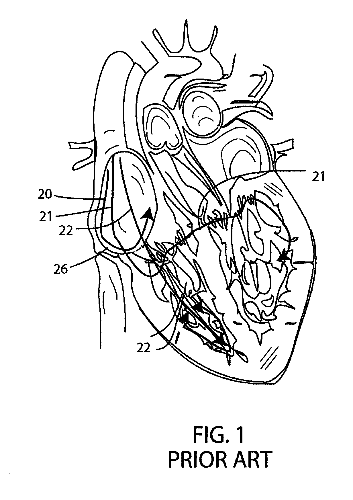
[0036]The invention encompasses all implantable electrostimulation devices with implanted wire leads, but is illustrated in the context of a cardiac pulsing device. Typically, a pacemaker is implanted just under the skin and on the left side of the chest, near the shoulder. The heart is protected beneath the ribs, and the pacemaker leads follow a somewhat tortuous path from the pacemaker under theclavicle and along the ribs down to the heart.

[0037]FIG. 1 shows schematically a human heart with some walls cut away. In FIG. 1 pacing leads are shown following a conventional path into the heart, and into the cardiac veins of the left ventricle, as has been typical of conventional practice and which, with some exceptions, is the basic path of leads of this invention.

[0038]In typical conventional practice, conductive leads 20, 21 and 22 are introduced into the heart through the superior vena cava 24, brought into the vena cava via subclavian or cephalic vein access points. For the right si...


PUM

PropertyMeasurementUnit
Lengthaaaaaaaaaa
Thicknessaaaaaaaaaa
Diameteraaaaaaaaaa

Abstract

A cardiac pacemaker, other CRT device or neurostimulator has one or more fine wire leads. Formed of a glass, silica, sapphire or crystalline quartz fiber with a metal buffer cladding, a unipolar lead can have an outer diameter as small as about 300 microns or even smaller. The buffered fibers are extremely durable, can be bent through small radii and will not fatigue even from millions of iterations of flexing. Bipolar leads can include several conductors side by side within a glass/silica fiber, or can be concentric metal coatings in a structure including several fiber layers. An outer protective sheath of a flexible polymer material can be included.

Description

RELATED PATENT DOCUMENTS[0001]This application is a continuation of U.S. patent application Ser. No. 12 / 932,782 filed Mar. 4, 2011; which is a continuation-in-part of U.S. patent applications, Ser. No. 12 / 156,129 (ABN) filed May 28, 2008, Ser. No. 12 / 584,837 filed Sep. 10, 2009 (which claimed benefit from provisional application Ser. No. 61 / 191,722 filed Sep. 10, 2008) and Ser. No. 12 / 590,851 filed Nov. 12, 2009 (which claimed benefit from provisional application Ser. No. 61 / 198,900 filed Nov. 12, 2008). This application incorporates by reference in its entirety U.S. patent application Ser. No. 12 / 584,837 filed Sep. 10, 2009 (U.S. Pub. No. 2010 / 0331941). This application also incorporates by reference in its entirety U.S. patent application Ser. No. 12 / 586,031 (U.S. Pub. No. 2010 / 0057179 published Mar. 4, 2010). In addition, the following unpublished applications are incorporated entirely herein: Ser. No. 12 / 590,851 filed Nov. 12, 2009, and Ser. No. 12 / 660,344 filed Feb. 23, 2010.BA...

Claims


Application Information

Patent Timeline
IPC IPC(8): A61N1/05B05D5/12H01R43/16
CPCY10T29/49204A61N1/056
Inventor ERB, JOHN L.ANDERSON, KIMBERLYLOVOI, PAUL A.
Owner CARDIA ACCESS
Why Eureka
Try Eureka