
Method of simultaneously manufacturing high quality naphthenic base oil and heavy base oil

Active Publication Date: 2013-02-28
SK INNOVATION CO LTD
View PDF1 Cites 35 Cited by
  • Summary
  • Abstract
  • Description
  • Claims
  • Application Information

AI Technical Summary

Benefits of technology

The present invention allows for the creation of products with low viscosity and heavy base oil with high viscosity using a single catalyst system. This results in economic benefits and efficient base oil production. The ratio of atmospheric residue and vacuum residue and the separation conditions of vacuum distillation can be adjusted to control the grade and production yield of final base oil, meeting the demands of the market. Additionally, the manufacturing process reduces environmental contaminants, resulting in high-quality base oil that is environmentally friendly and has a high yield compared to conventional methods.

Problems solved by technology

However, the heavy base oil thus manufactured has relatively high aromatic content and thus becomes unstable, and also may not satisfy a polycyclic aromatic (PCA) standard which becomes strictly restricted in recent years.
Furthermore, because it is manufactured using solvent extraction, the production yield of base oil is low (on the order of 40˜50%), environmental contaminants are discharged in a large amount, and an additional process is required to satisfy the PCA regulation standard (<3%).
Because of environmental problems and economical inefficiency, the number of plants that manufacture the base oil of Group I using solvent extraction is rapidly decreasing these days.
Accordingly, the supply of heavy base oil products falls short of the demand for them.
However, because it is difficult to obtain heavy base oil having high viscosity such as 150BS or the like using conventional methods, limitations are imposed on obtaining heavy base oil products ranging from low viscosity to high viscosity using a single reaction process.

Method used


Image

  • Method of simultaneously manufacturing high quality naphthenic base oil and heavy base oil
  • Method of simultaneously manufacturing high quality naphthenic base oil and heavy base oil

Examples


example 1

Manufacture of Base oil from Effluent of FCC

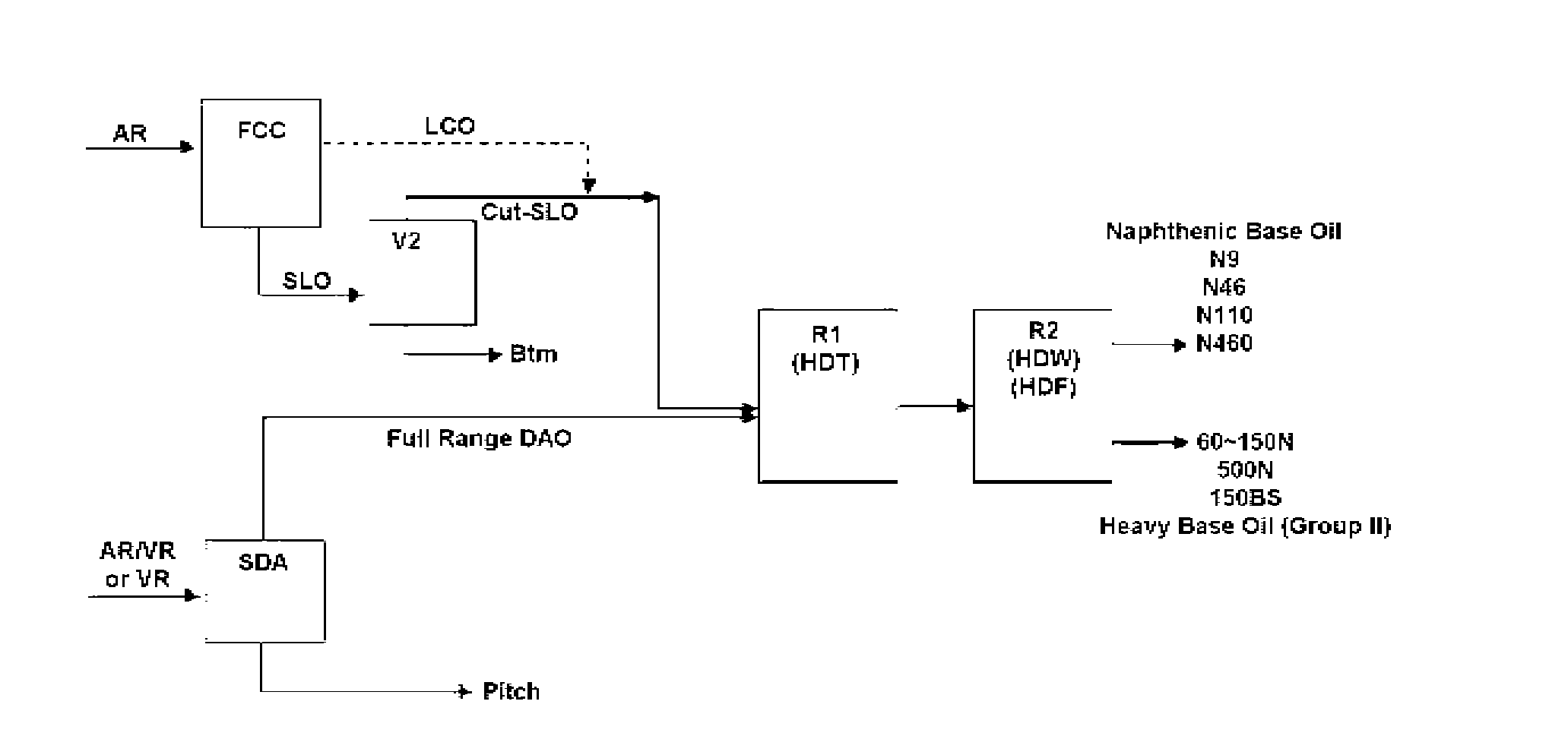
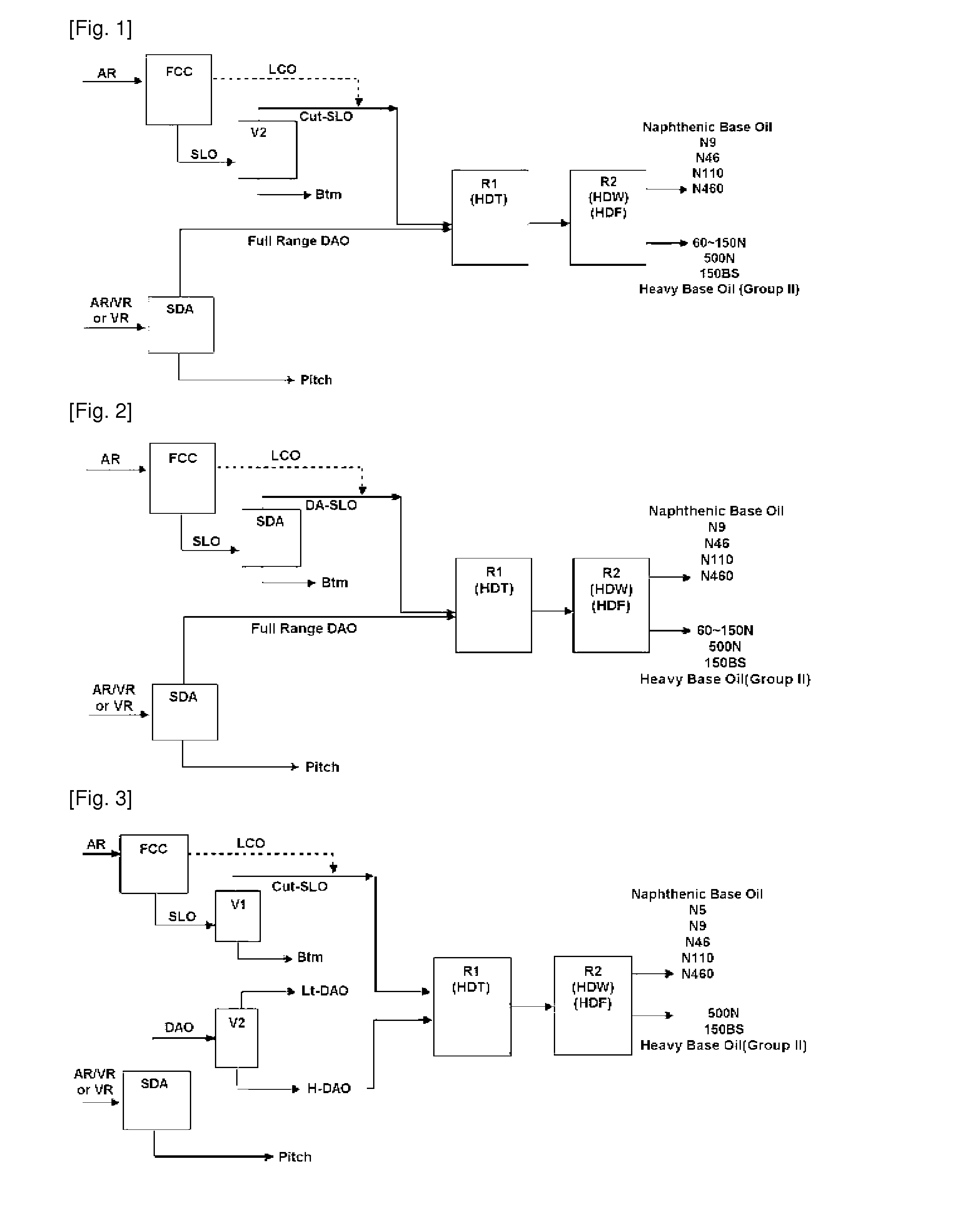
[0053]Among Cut-SLO fractions of Table 1, Cut-1 and Cut-2 were mixed at a volume ratio of 6:4 thus preparing a feedstock, which was then subjected to HDT under conditions including an LHSV of 0.5 hr−1, a pressure of 150 kg / cm2g, a reaction temperature of 370° C. and a hydrogen to oil ratio of 1500 NL / L in the presence of a commercially available catalyst having activities of hydrodesulfurization (HDS), hydrodenitrogenation (HDN) and hydrodemetallization (HDM), so that sulfur and nitrogen were reduced to 100 ppm or less and 10 ppm or less, respectively.

[0054]Subsequently, the oil fraction obtained after HDT was subjected to Catalytic dewaxing (CDW) unit using an isomerization catalyst comprising Pt / zeolite and to HDF using an HDF catalyst composed of (Pt / Pd) / Al2O3. The CDW and HDF were performed under conditions including a reaction pressure of 140˜150 kg / cm2g, an LHSV of 1.0˜2.0 hr−1, and a hydrogen to oil ratio of 400˜600 Nm3 / m3. As such,...

example 2

Manufacture of Base Oil from Effluent (H-DAO subjected to Vacuum Distillation) of SDA

[0057]Heavy base oil (500N / 150BS or the like) was manufactured at high yield under the same (single) catalyst / process conditions as when manufacturing the naphthenic base oil from Cut-SLO. Specifically, heavy deasphalted oil (H-DAO) shown in Table 2 was subjected to HDT under conditions including an LHSV of 0.5˜1.0 hr−1, a pressure of 150 kg / cm2g, a reaction temperature of 350˜360° C. and a hydrogen to oil ratio of 1,000˜1500 NL / L in the presence of a commercially available catalyst having activities of HDS, HDN and HDM, so that sulfur and nitrogen were reduced to 50 ppm or less and 5 ppm or less, respectively.

[0058]Subsequently, the oil fraction obtained after HDT was subjected to CDW using an isomerization catalyst comprising Pt / zeolite and to HDF in the presence of an HDF catalyst composed of (Pt / Pd) / Al2O3. The reaction was performed under conditions including a reaction pressure of 140˜150 kg / cm...

example 3

Manufacture of Base Oil from Effluent (DAO not subjected to Vacuum Distillation) of SDA

[0061]Base oil was manufactured from DAO (not subjected to vacuum distillation) under the same (single) catalyst / process conditions as when manufacturing the naphthenic base oil and heavy base oil from Cut-SLO and H-DAO. Specifically, Full Range DAO shown in Table 2 was subjected to HDT under conditions including an LHSV of 0.5˜1.0 hr−1, a pressure of 150 kg / cm2g, a reaction temperature of 350˜360° C. and a hydrogen to oil ratio of 1,000˜1500 NL / L in the presence of a commercially available catalyst having activities of HDS, HDN and HDM, so that sulfur and nitrogen were reduced to 50 ppm or less and 5 ppm or less, respectively.

[0062]Subsequently, the oil fraction obtained after HDT was subjected to CDW using an isomerization catalyst comprising Pt / zeolite and to HDF in the presence of an HDF catalyst composed of (Pt / Pd) / Al2O3. The reaction was performed under conditions including a reaction pressu...


PUM

PropertyMeasurementUnit
Temperatureaaaaaaaaaa
Kinematic viscosityaaaaaaaaaa

Abstract

Disclosed is a method of simultaneously manufacturing high quality naphthenic base oil and heavy base oil using a single catalyst system, by subjecting an oil fraction (slurry oil or light cycle oil) produced by fluid catalytic cracking and an oil fraction (deasphalted oil) produced by solvent deasphalting to hydrotreating, catalytic dewaxing and hydrofinishing of the single catalyst system, thereby obtaining not only products having low viscosity but also heavy base oil products (150BS) having high viscosity which was impossible to obtain using a conventional catalytic reaction process, and also thereby producing base oil products having different properties using the single catalyst system, thus generating economic benefits and exhibiting superior efficiency.

Description

TECHNICAL FIELD[0001]The present invention relates to a method of simultaneously manufacturing high quality naphthenic base oil and heavy base oil using a single catalyst system.BACKGROUND ART[0002]Conventional heavy base oil products (e.g. 500N, 150BS, etc.) (Group I) having high viscosity have been typically manufactured by subjecting a mixture of atmospheric residue and vacuum residue or vacuum residue to solvent deasphalting process (SDA), thus obtaining deasphalted oil (DAO) having neither asphaltene nor impurities, and then subjecting the deasphalted oil to solvent extraction.[0003]However, the heavy base oil thus manufactured has relatively high aromatic content and thus becomes unstable, and also may not satisfy a polycyclic aromatic (PCA) standard which becomes strictly restricted in recent years. Furthermore, because it is manufactured using solvent extraction, the production yield of base oil is low (on the order of 40˜50%), environmental contaminants are discharged in a ...

Claims


Application Information

Patent Timeline
IPC IPC(8): C10G69/04
CPCC10G55/08C10G67/0463C10G69/04C10M101/02C10M2203/1065C10M2203/1085C10M2203/02C10G2300/4018C10G2300/107C10G2300/1077C10G2300/302C10G2400/10C10N2230/02C10G65/043C10N2030/02B01J23/42B01J23/44B01J29/06C10G11/18C10G65/14C10G2300/206C10M171/02
Inventor NOH, KYUNG SEOKRYU, JAE WOOKKIM, DO HYOUNKIM, GYUNG ROKLEE, SEUNG WOOKIM, DO WOANCHOI, SUNOH, SEUNG HOONYOON, BYUNG WONCHUN, BUM SUK
Owner SK INNOVATION CO LTD
Learn More