Process for producing tubular ceramic structures of non-circular cross section

Active Publication Date: 2013-03-07
WATT FUEL CELL CORP
View PDF3 Cites 25 Cited by
  • Summary
  • Abstract
  • Description
  • Claims
  • Application Information

AI Technical Summary

Benefits of technology

[0013]d) heat shrinking the mandrel component of the mandrel-tubular ceramic structure assembly to cause the mandrel to undergo shrinkage to a reduced size in which the external surface of the mandrel separates from the interior surface of the tubular ceramic structure of non-circular cross section facilitating removal of the mandrel therefrom.
[0014]A major advantage and benefit of the foregoing process for producing a tubular ceramic structure of non-circular cross section lies in its ability to provide ceramic or cermet bodies over a wide range of ratios of length to external diameter and ratios of external diameter to wall thickness while meeting very precise predetermined dimensional tolerances.
[0015]Another advantage of the process herein for producing a tubular ceramic structure of non-circular cross section is its capability for readily and conveniently varying, or mod

Problems solved by technology

Each of these techniques for producing tubular ceramic structures generally, and tubular components of SOFCs in particular, is subject to certain inherent drawbacks and/or limitations.
This practical requirement tends to limit the usefulness of extrusion methods to the production of relatively thick-walled tubular ceramic structures.
The requirement for a relatively thick-walled extrudate, which can only be achieved with an extrudable material of fairly high viscosity, e.g., one of paste- or putty-like consistency, imposes yet another limitation on the usefulness of extrusion methods for the manufacture of tubular ceramic structures, namely, the need to carefully and completely dry the extrudate before subjecting it to such high temperature downstream processes as the burning out of organics (i.e., residual solvent(s), dispersant(s), binder(s), etc.) and sintering.
Too rapid drying and/or insufficient drying can result in the production of mechanical defe

Method used


Image

  • Process for producing tubular ceramic structures of non-circular cross section
  • Process for producing tubular ceramic structures of non-circular cross section
  • Process for producing tubular ceramic structures of non-circular cross section

Examples


example

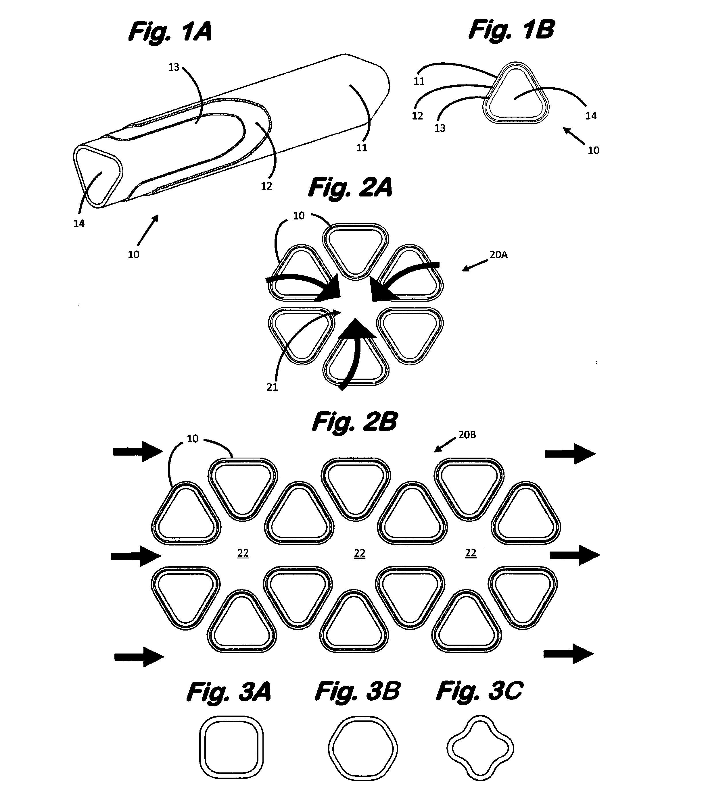
[0077]A green state tubular anode having the cross section of an equilateral triangle with rounded vertices is produced possessing the following dimensions: length of 230 mm, cross-sectional area of about 31.5 mm2 and wall thickness of 0.50 mm.

[0078]An anode-forming composition in the form of an organic solvent slurry is provided by combining the following ingredients in the indicated amounts:

ComponentAmount (g)8-mol % yttrium zirconium oxide powder2.10NiO powder3.90methylethylketone (MEK)10.0polyvinylpyrrolidone (PVP) powder2.00

[0079]The tubular anode is produced from the foregoing anode-forming composition employing the following operations.

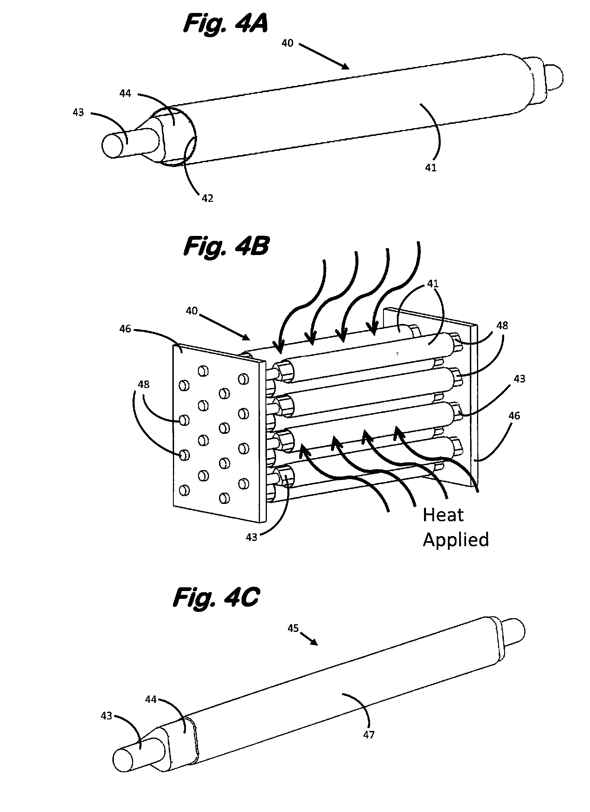
[0080](a) Forming the Triangularly Shaped Mandrel-Spindle Assembly

[0081]Stock heat-shrinkable polyethylene terephthalate (PET) cylindrical tubing having an outside diameter of 7.6 mm is divided into 230 mm lengths with each tubular section being weighed to within ±0.01 g accuracy. A triangularly shaped spindle of 305 mm length clad with a frict...


PUM

PropertyMeasurementUnit
Temperatureaaaaaaaaaa
Viscosityaaaaaaaaaa
Viscosityaaaaaaaaaa

Abstract

Tubular ceramic structures of non-circular cross section, e.g., anode components of tubular fuel cells of non-circular cross section, are manufactured by applying ceramic-forming composition to the external non-circular surface of the heat shrinkable polymeric tubular mandrel component of a rotating mandrel-spindle assembly, removing the spindle from said assembly after a predetermined thickness of tubular ceramic structure of non-circular cross section has been built up on the mandrel and thereafter heat shrinking the mandrel to cause the mandrel to separate from the tubular ceramic structure of non-circular cross section.

Description

BACKGROUND OF THE INVENTION[0001]This invention relates to a process for producing tubular ceramic structures of non-circular cross section, to patterned arrays of such structures, in particular, of non-circular tubular anode-supported solid oxide fuel cell (SOFC) units, and to SOFC devices incorporating patterned arrays of non-circular tubular SOFC units.[0002]Tubular ceramic structures are known for use as heat exchangers where corrosive liquids or gases are encountered, recuperators, catalyst bodies, as components of fuel cells devices, particularly SOFC devices, and in a variety of other applications.[0003]Tubular ceramic structures can be produced in a broad range of lengths, wall thicknesses and cross-sectional areas and geometries employing any of several known and conventional techniques such as extrusion and clip coating. Each of these techniques for producing tubular ceramic structures generally, and tubular components of SOFCs in particular, is subject to certain inherent...

Claims


Application Information

Patent Timeline
IPC IPC(8): H01M8/24B28B1/32H01M4/04H01M8/04B28B1/30
CPCB28B21/88B28B21/905C23C24/04H01M8/243H01M8/2485H01M4/8814Y02E60/525H01M8/004B28B7/30B28B7/348B28B21/44H01M8/1246Y02E60/521H01M4/886C23C4/123C23C4/06C23C4/185C23C24/00C23C30/00Y02P40/60Y02E60/50H01M8/2484H01M8/0273Y02P70/50
Inventor FINNERTY, CAINE M.EMLEY, BENJAMIN J.
Owner WATT FUEL CELL CORP
Why Eureka
Try Eureka