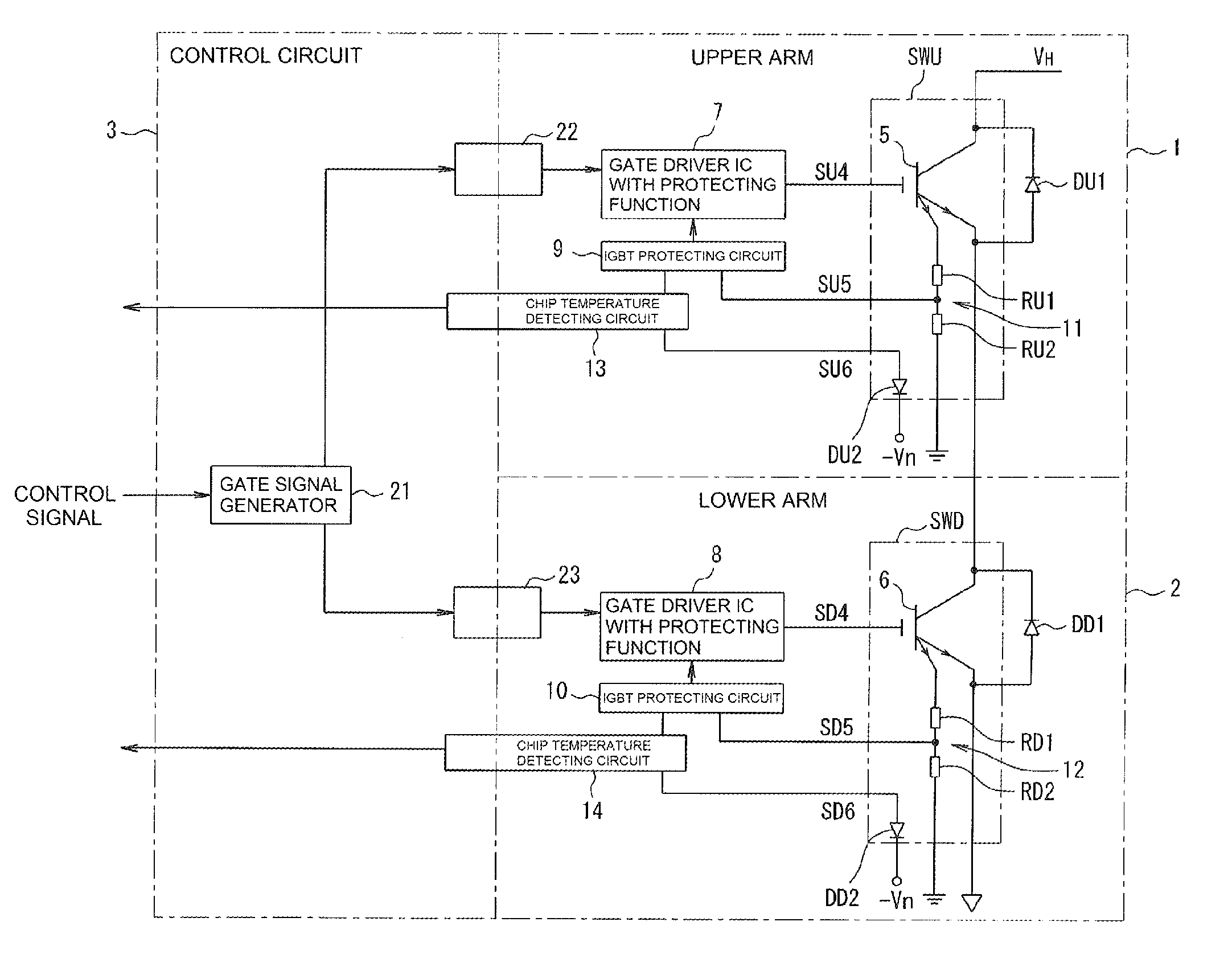
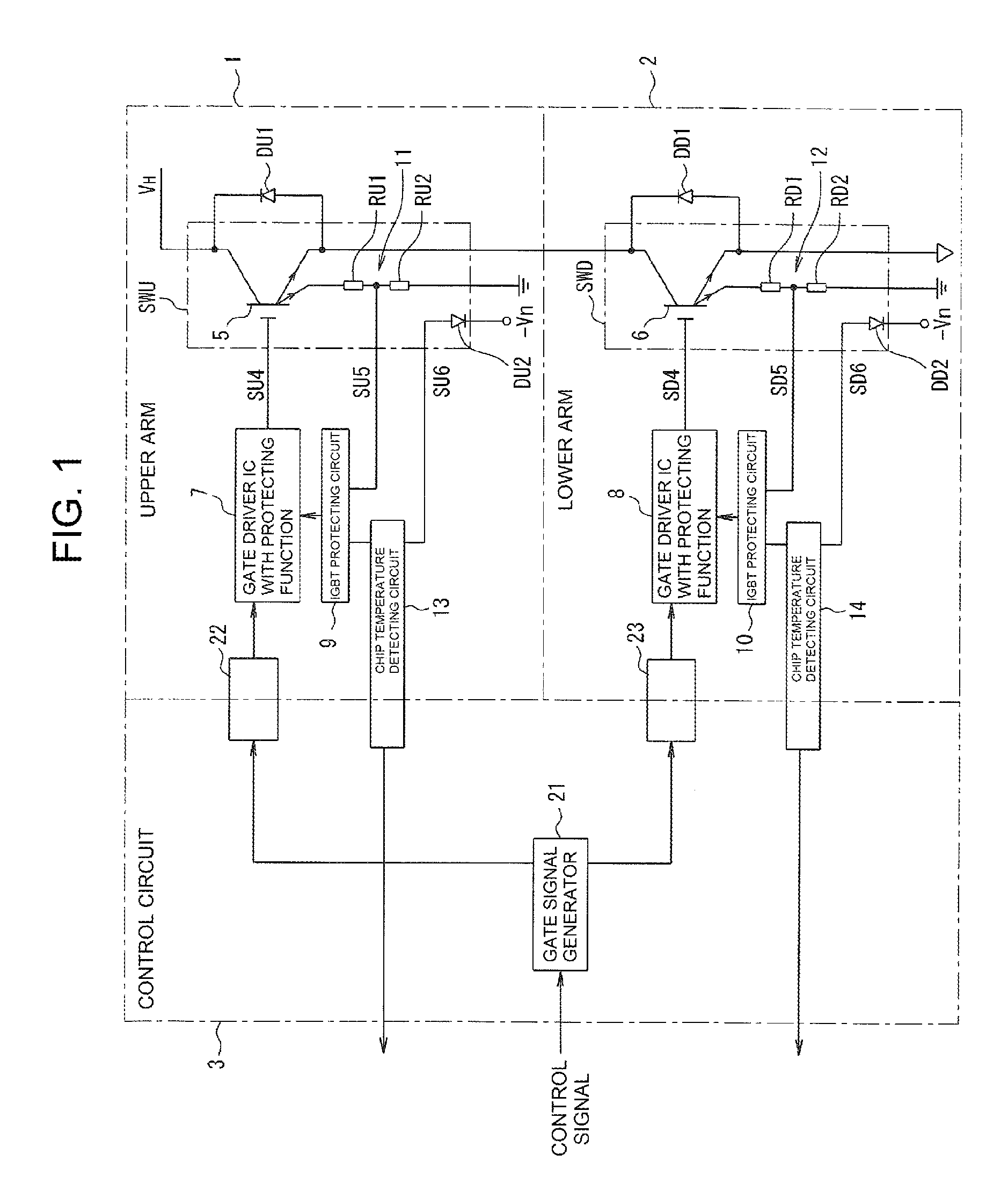
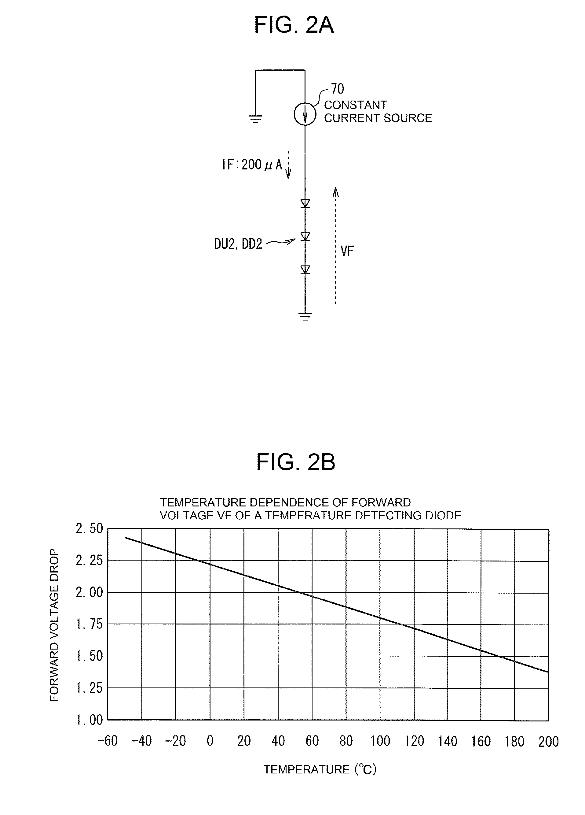
Temperature measuring device of a power semiconductor apparatus

a technology of temperature measurement and power semiconductor, which is applied in the direction of heat measurement, pulse technique, instruments, etc., can solve the problems of increasing calculation operation load, affecting the accuracy of measurement results, so as to reduce the calculation operation load and calculate easily. , the effect of simple operation

Active Publication Date: 2013-03-07
FUJI ELECTRIC CO LTD
View PDF7 Cites 47 Cited by
  • Summary
  • Abstract
  • Description
  • Claims
  • Application Information

AI Technical Summary

Benefits of technology

[0086]According to the present invention, in calibration processing, a reference voltage source is connected in place of a temperature detecting diode and a plurality of known reference voltages are applied by the reference voltage source. A gradient of a line segment connecting a point of a measured value of an A/D converter for one of the reference voltages and a point of another measured value of the A/D converter for another of the reference voltages is calculated and stored in a memory. An offset correction value, which is one of the measured values of the A/D converter, is also recorded in the memory. In temperature measurement processing with the temperature detecting diode, correction operation is exe...

Problems solved by technology

This adjusting procedure requires a costly laser trimming device and some man-hours for resistance adjusting work, thus leading to higher manufacturing cost.
Because re-adjustment is impossible once the trimming is conducted, an additional unsolved problem is present in that the procedure involves to some extent a percentage of defecti...

Method used


Image

  • Temperature measuring device of a power semiconductor apparatus
  • Temperature measuring device of a power semiconductor apparatus
  • Temperature measuring device of a power semiconductor apparatus

Examples


first embodiment

[0169]Now, operation of the first embodiment according to the present invention will be described in the following.

[0170]To execute calibration processing of the chip temperature detecting circuit 13 (or 14) in an adjusting operation step for the intelligent power module, a constant voltage source 110 that can deliver voltage values VF1 and VF2 according to a voltage application instruction is first connected as shown in FIG. 5 in place of a temperature detecting diode DU2 (or DD2).

[0171]In this state, the start switch 109 for the calibration processing in the microcomputer 102 is turned ON to start the calibration processing as shown in FIG. 7 in the central processing unit 104.

[0172]The turning ON of the start switch 109 for calibration processing proceeds the calibration processing from the step S1 to the step S2, in which an instruction is given to the constant voltage source 110 to apply a voltage value VF1 corresponding to a temperature of 155° C.

[0173]According to the instruc...

second embodiment

[0189]Next, a second embodiment according to the present invention will be described in the following with reference to FIG. 10.

[0190]In the second embodiment, the A / D converter is disposed not at the side of the microcomputer 102, but next to the temperature detecting diode and the forward voltage of the diode is directly converted to a digital data.

[0191]In the construction of the second embodiment shown in FIG. 10, the forward voltage VF of the temperature detecting diode DU2 (or DD2) undergoes direct digital conversion in the A / D converter 120 to output a measurement value, which is transmitted through a serial transmission unit 130 installed in a low function microcomputer, and delivered to the gate of a field effect transistor 81.

[0192]As a result, the PWM-analogue conversion circuit 91 shown in FIG. 3 can be removed leaving solely a binarization circuit 92. The binary signal delivered by the binarization circuit 92 directly enters an interface circuit 103 of microcomputer 102...


PUM


Abstract

A temperature measuring device of a power semiconductor apparatus that accurately detects chip temperature even where a gradient of the measured characteristic line segment is different from a designed gradient, including a chip temperature detecting circuit that includes an A/D converter delivering a measurement value of a digital converted forward voltage across a temperature detecting diode and an operational processing unit for calibration and chip temperature calculation. In calibration processing, different known reference voltages are applied by a reference connected in place of the diode and a gradient of the line segment connecting the measurement values is calculated. The gradient is stored in a memory with an offset correction value that is one of the measurement values. A chip temperature is calculated based on a forward voltage across the diode calculated based on the measurement value and the stored values of the gradient and the offset correction value.

Description

CROSS-REFERENCE TO RELATED APPLICATION[0001]This application is based on, and claims priority from Japanese Patent Application No. 2011-194942, filed on Sep. 7, 2011, the contents of which are incorporated herein by reference.BACKGROUND OF THE INVENTION[0002]1. Field of the Invention[0003]The present invention relates to a temperature measuring device for a semiconductor apparatus installed in voltage converters for electronic systems of vehicles or the like.[0004]2. Description of the Related Art[0005]In recent onboard apparatus, a vehicle driving system 1100, as shown in FIG. 11, having an electric motor 1104 to generate driving force, may include the main sections of a power supply 1101, a buck-boost converter 1102, and an inverter 1103, to achieve high efficiency and energy saving. The three phase motor 1104 is a motor when it drives a vehicle, but becomes a generator when it brakes the vehicle. The arrow Y1 indicates the direction of energy flow when the vehicle is driven and t...

Claims


Application Information

Patent Timeline
IPC IPC(8): G01K15/00G06F19/00
CPCG01K3/14G01K7/01H03K2017/0806G01K2219/00G01K15/005
Inventor YOSHIMURA, HIROYUKI
Owner FUJI ELECTRIC CO LTD
Why Eureka
Try Eureka