Method for coating oxidation protective layer for carbon/carbon composite, carbon heater, and cooker

a technology of oxidation protective layer and carbon/carbon composite, which is applied in the direction of coating, ohmic-resistance heating, ohmic-resistance electrode, etc., can solve the problems of pure carbon fibers not suitable for use in these applications, oxidation (ablation) of materials, and inability to meet the requirements of oxidation resistance and heat ablation resistance of carbon fiber composites, and achieves high thermal stability and oxidation resistance. ,

Active Publication Date: 2013-03-28
LG ELECTRONICS INC
View PDF13 Cites 4 Cited by
  • Summary
  • Abstract
  • Description
  • Claims
  • Application Information

AI Technical Summary

Benefits of technology

[0013]According to an embodiment, the oxidation of carbon fibers is prevented at a high temperature in air, and thus heat and ablation resistances of a carbon fiber composite are improved. Thus, the carbon fiber composite may have high thermal stability and oxidation resistance when it is in air.
[0014]Also, according to an embodiment, the carbon fiber composite may have a uniform coating layer. Therefore, a peeling of the coating layer which may be generated due to a difference in coefficient of thermal expansion between the coating layer and the surface of carbon fiber under iterative thermal history may be prevented.
[0015]Furthermore, according to

Problems solved by technology

However, although carbon fibers (CFs) have favorable engineering properties, a surface of carbon fiber are oxidized by reacting with oxygen when exposed to air at a temperature of 500° C. or more, or gases such as CO or CO2 are generated, resulting in an erosion (ablation) of material.
Thus, pure carbon fibers are not suitable for use in these applications.
Further, a decrease in weight and strength of carbon fibers thereby may limit their applications.
The former can inhibit o

Method used


Image

  • Method for coating oxidation protective layer for carbon/carbon composite, carbon heater, and cooker
  • Method for coating oxidation protective layer for carbon/carbon composite, carbon heater, and cooker
  • Method for coating oxidation protective layer for carbon/carbon composite, carbon heater, and cooker

Examples


Embodiment Construction

[0029]Hereinafter, a method for coating an oxidation protective layer for a carbon / carbon composite according to the present invention will be described in detail with reference to the accompanying drawings and embodiments.

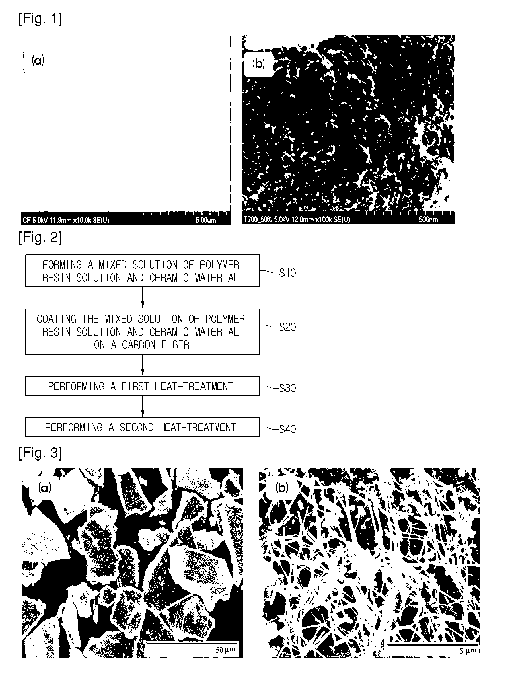
[0030]FIG. 2 is a flow chart showing processes for manufacturing a carbon fiber composite coated with a mixed solution comprising ceramic powders according to the present invention.

[0031]Regarding FIG. 2, first, a polymer resin is dissolved in a solvent to form a solution of polymer resin, and ceramic powders are dispersed and mixed with the solution of polymer resin (S10). Thus, ceramics having a relatively low adhesive force to carbon fibers may be stably deposited on the surface of carbon fiber.

[0032]That is, in the case of carbon fibers formed at a high temperature, the number of functional groups on the surface of carbon fiber which can enhance a bonding force to a matrix is relatively less, and thus an adhesive force to ceramics become very weak. Therefore, ...


PUM

PropertyMeasurementUnit
Temperatureaaaaaaaaaa

Abstract

The present invention provides an oven range. In the present invention, a method for coating an oxidation protective layer for a carbon/carbon composite, comprising: dissolving a polymer resin in a solvent to form a solution of polymer resin; dispersing ceramic powders in the solution of polymer resin to form a mixed solution; coating the mixed solution on a carbon fiber; performing a first heat-treatment to treat the carbon fiber by heat in air; and performing a second heat-treatment to treat the carbon fiber by heat under an inert gas.

Description

TECHNICAL FIELD[0001]The present disclosure relates to a carbon / carbon composite, and more particularly, to a method for coating an oxidation protective layer for the carbon / carbon composite, and a carbon heater prepared thereby and a cooker having the carbon heater.BACKGROUND ART[0002]Carbon fibers (CFs) are materials comprising 92% or more carbon, and having high values in thermal conductivity, specific strength and elasticity, and low values in modulus of elasticity, coefficient of thermal expansion and density. Also, carbon fibers are materials suitable for use in a high temperature structure by virtue of relatively good processability, and in particular, interest in carbon fibers as a reinforcing material for high-tech composites having high processability is increasing. In addition, carbon fibers are highly resistant to thermal shock, and thus have been widely used in various industry fields as materials for an ultra-high temperature structure such as friction materials for ai...

Claims


Application Information

Patent Timeline
IPC IPC(8): B05D3/02H05B3/03
CPCC04B41/009C04B2235/528C04B41/5061C04B41/5066C04B41/87H05B3/145C04B41/5059C04B2235/5248C04B35/63444C04B35/63416C04B35/62892C04B35/62889C04B35/6264C04B35/6263C04B2235/9684C04B2235/5445C04B35/83C04B35/62886C04B35/62871C04B35/62863B05D3/0209H05B3/03C04B35/6286C04B41/0072C04B41/4517C04B41/4539H05B3/10H05B3/42C04B41/52
Inventor LEE, YOUNGJUNYANG, KABSEUNGYOON, JEONGHYUNKIM, CHANGHYOKIM, SOOYEONCHO, SEONGHOKIM, BOHYE
Owner LG ELECTRONICS INC
Why Eureka
Try Eureka