Film mirror for reflecting sunlight and reflective device for solar thermal power generation

Inactive Publication Date: 2013-04-04
KONICA MINOLTA OPTO
View PDF7 Cites 10 Cited by
  • Summary
  • Abstract
  • Description
  • Claims
  • Application Information

AI Technical Summary

Benefits of technology

[0024]The present invention can provide a film mirror for reflecting sunlight which can be manufactured with simple production equipment and has a high regular reflect

Problems solved by technology

Global warming in recent years has developed into such a serious situation as to threaten even the survival of mankind in the future.
Accordingly, in the near future, we may no longer be allowed to continue use of fossil fuels at the current rate.
Although solar energy is a significantly promising alternative energy, it has disadvantages of (1) low energy density and (2) difficulties in storage and transport from the viewpoint of its utilization.
Although glass mirrors are highly durable for various environments, they have disadvantages such as damage during transport and significantly high weights in large sizes, leading to high plant construction costs for providing necessary strength of mounts on which the mirrors are installed.
Furthermore, glass mirrors are so fragile that workers should concern about avoiding injury by fragments when replacing them.
Moreover, glass mirrors are often installed indoors and are affected by working environments (e.g., wind, rain, sand and dust); hence, the workers must have mature techniques to replace them.
In one case where a resin film is used as a film mirror for reflecting sunlight for solar thermal power generation (hereafter also referred to as a “sunlight reflective film mirror”, “film mirror” or simply “mirror”), however, problems such as degradation of the overall reflectance and regular reflectance due to various factors

Method used


Image

  • Film mirror for reflecting sunlight and reflective device for solar thermal power generation
  • Film mirror for reflecting sunlight and reflective device for solar thermal power generation
  • Film mirror for reflecting sunlight and reflective device for solar thermal power generation

Examples


example 1

Example 1

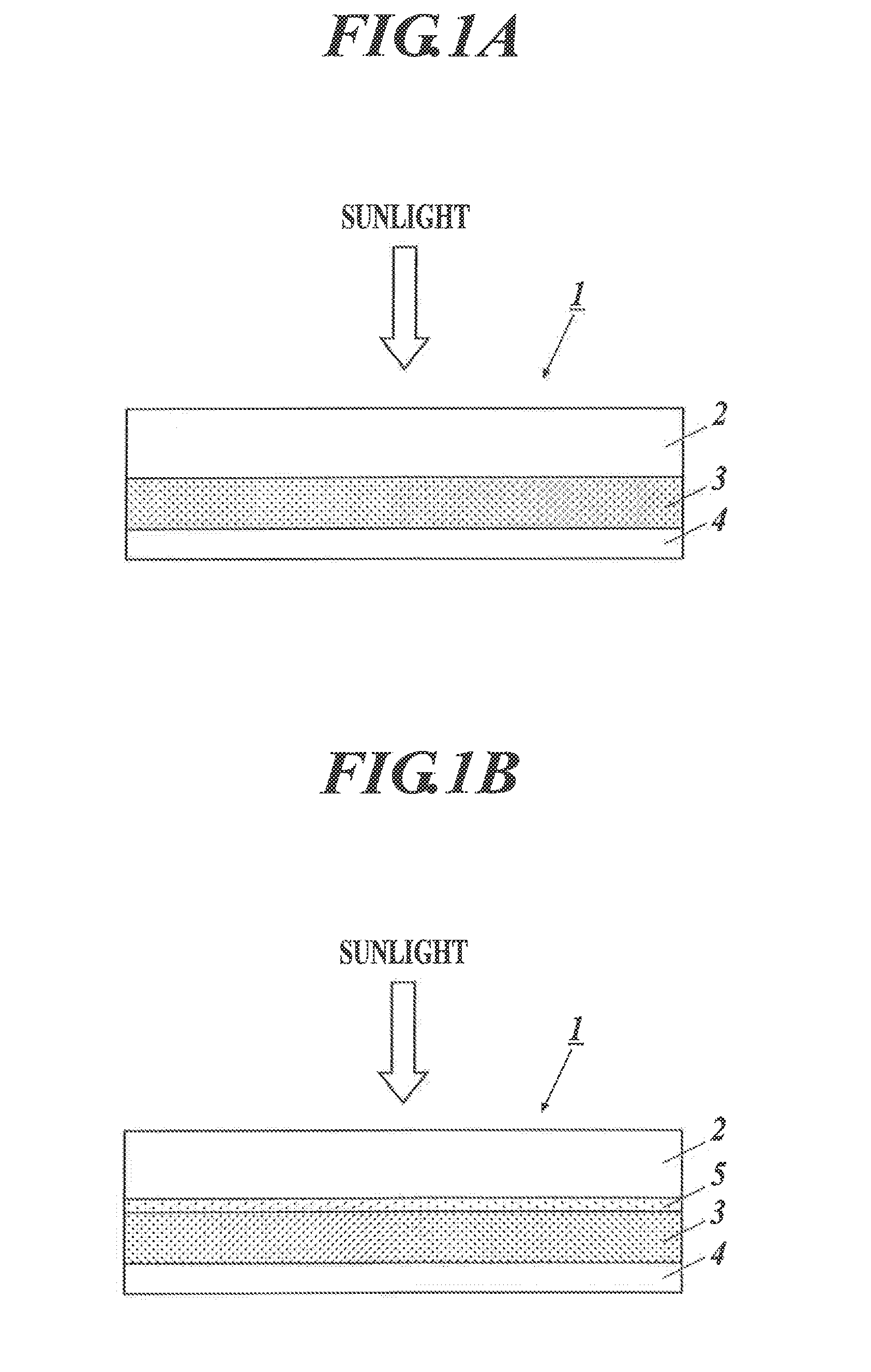
Preparation of Film Mirror for Reflecting Sun light

Preparation of Film Mirror 1: Comparative Example

Preparation of Polymer Film Substrate 1

[0142]A biaxially oriented polyester film (polyethylene terephthalate film) having a thickness of 60 μm was used as a polymer film substrate 1.

(Preparation of Silver Reflective Layer Coating Liquid 1 Containing Silver Complex Compound)

[0143]In a 500 ml Schlenk flask equipped with a stirrer, 2-ethylhexylammonium 2-ethylcabamate (referred to as Compound 1 in Table 1) (65.0 g, 215 mmol) as an ammonium carbamate compound was dissolved in 2-propanpl (150.0 g), and then silver oxide (20.0 g, 86.2 mmol) as a silver compound was added to react at room temperature. The reaction mixture, which was initially black suspension, faded gradually into a transparent solution as the reaction proceeded with the formation of a silver complex compound. Two hours later, the solution turned completely colorless and transparent. To this solution, 2-hydrox...

example 2

Preparation of Reflective Device for Solar Thermal Power Generation

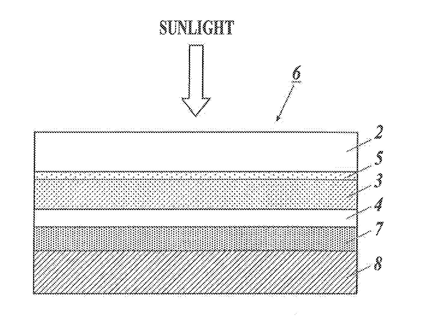
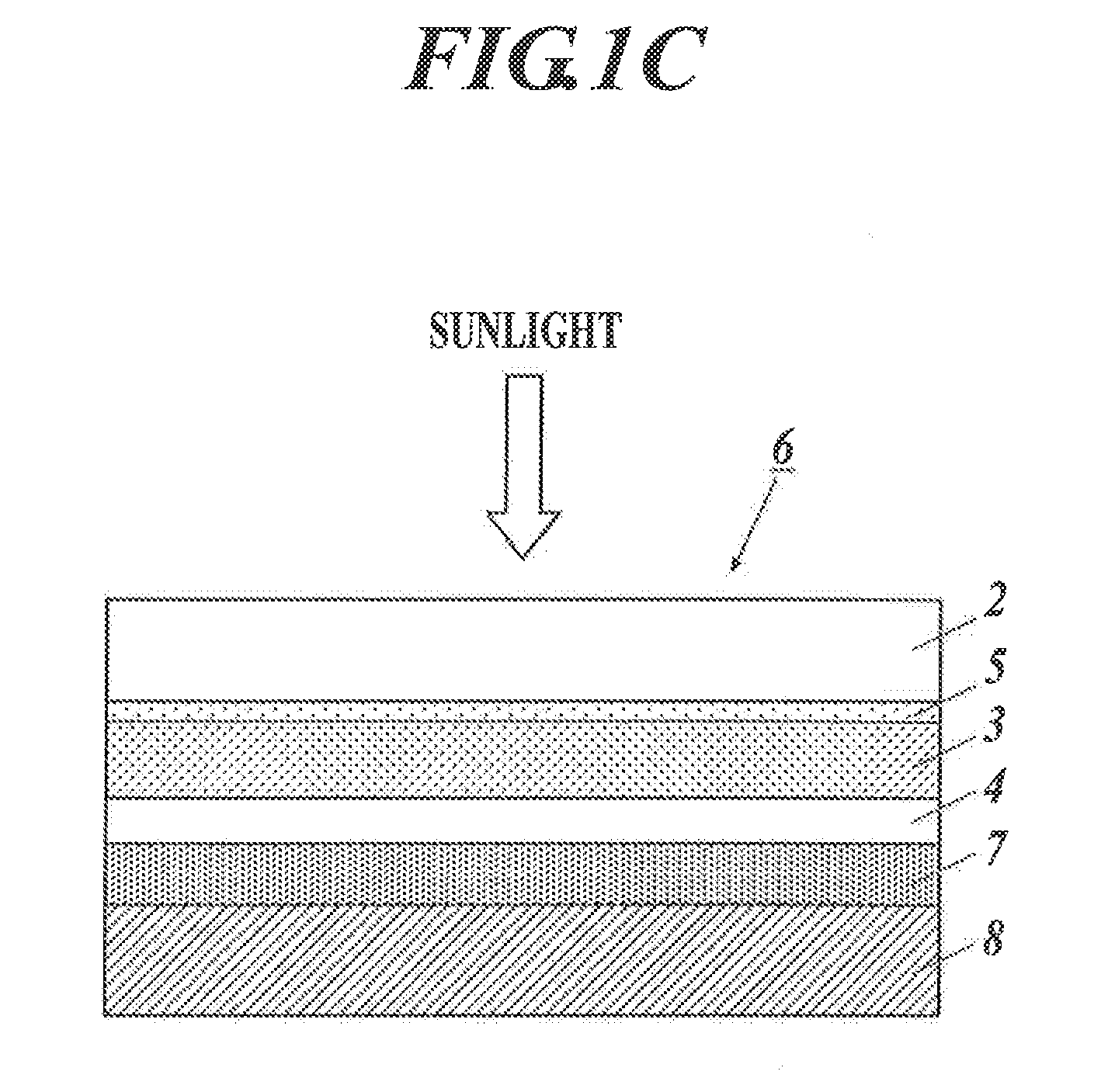
[0174]An acrylic adhesive S-dine (™) ™7851 (manufactured by Sekisui Chemical Co., Ltd.) was applied onto the surface opposite to the sunlight incident surface of each film mirror in an amount such that the thickness of coating became 5 μm to form an adhesive layer. The adhesive layer was then bonded to an aluminum support of 1 mm thickness to prepare a reflective device for solar thermal power generation.

(Evaluation of Reflective Device for Solar Thermal Power Generation)

[0175]Regular reflectance, abrasion resistance, weather resistance and durability properties in a variety of temperature and humidity environments were evaluated in the same manner as in Example 1. The results show that the reflective devices for solar thermal power generation of the present invention have superior properties compared with the comparative examples.


PUM


Abstract

A film mirror for reflecting sunlight includes a polymer film substrate, a reflective layer including silver coating, and a protective coating layer in sequence from the incident side of sunlight. The reflective layer is formed by coating and calcining (firing) a coating liquid containing a silver complex compound.

Description

TECHNICAL FIELD[0001]The present invention relates to a film mirror for reflecting sunlight including a reflective layer provided with silver coating, and a reflective device for solar thermal power generation including the film mirror.BACKGROUND ART[0002]Global warming in recent years has developed into such a serious situation as to threaten even the survival of mankind in the future. The main cause of global warming has been believed to be atmospheric carbon dioxide (CO2) emitted from fossil fuels which have been used in large amounts as energy sources in the 20th century. Accordingly, in the near future, we may no longer be allowed to continue use of fossil fuels at the current rate. At the same time, depletion of natural gas and oil, which was believed to be inexhaustible in the past, seems to become more likely due to increasing energy demand accompanied by the rapid economic growth of so-called developing countries, e.g., China, India, and Brazil.[0003]Examples of the current...

Claims


Application Information

Patent Timeline
IPC IPC(8): G02B5/08F24J2/10F24S23/70
CPCG02B5/0808F24J2/1057G02B5/0891G02B5/0858F24J2002/1076Y02E10/40H01L31/0547Y02E10/52F24S2023/87F24S23/82
Inventor HONDA, MIKA
Owner KONICA MINOLTA OPTO
Why Eureka
Try Eureka