
Light-reflective anisotropic conductive adhesive and light emitting device

a technology of anisotropic conductive adhesives and light emitting devices, which is applied in the direction of non-metal conductors, conductors, non-macromolecular adhesive additives, etc., can solve the problems of significant reduction of light reflectance and total luminous flux of led, light emission efficiency of led element b>33/b>, and and achieves low wavelength dependence of light reflective properties to visible ligh

Active Publication Date: 2013-04-11
DEXERIALS CORP
View PDF2 Cites 16 Cited by
  • Summary
  • Abstract
  • Description
  • Claims
  • Application Information

AI Technical Summary

Benefits of technology

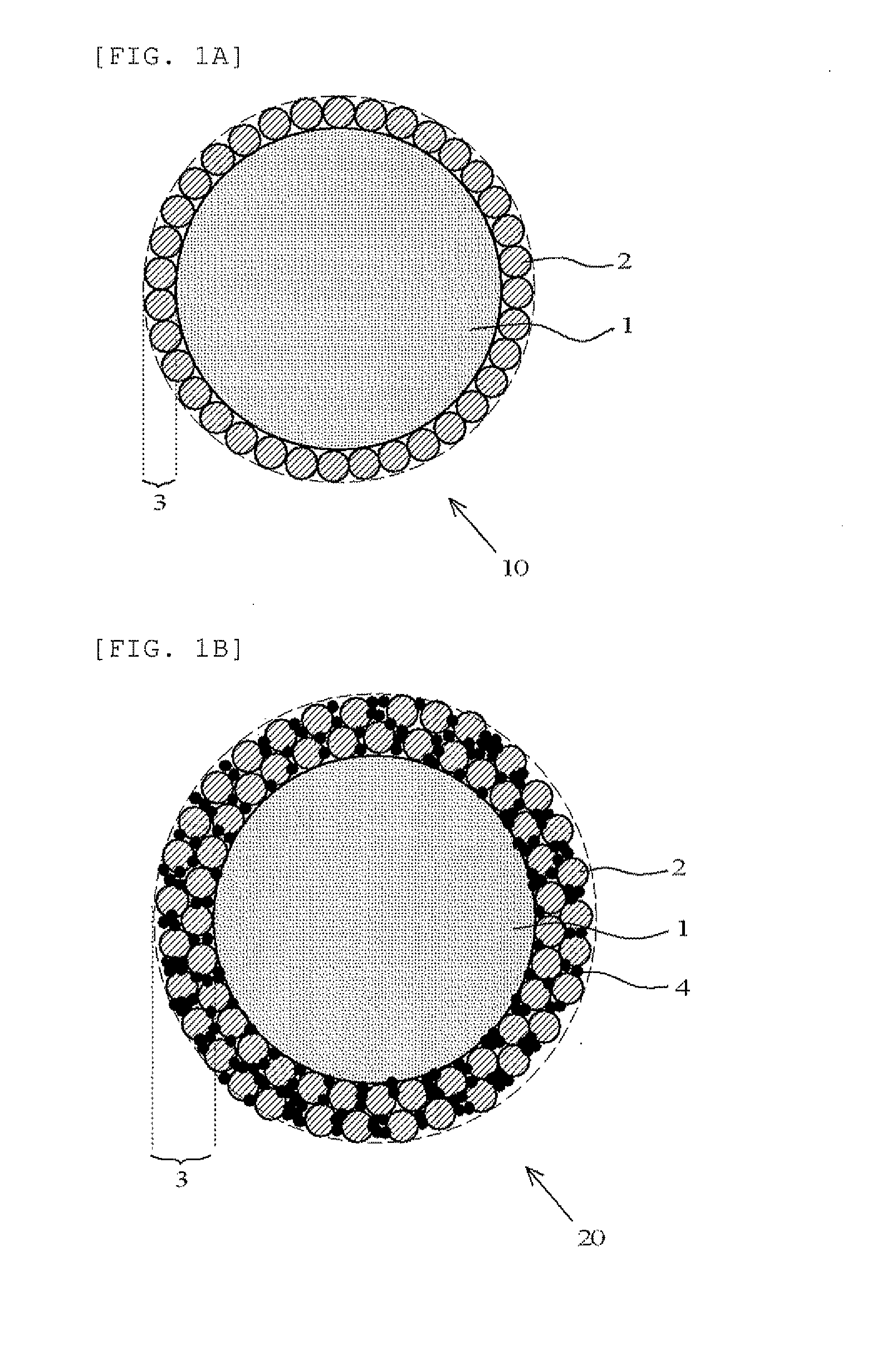
The present invention is a light-reflective anisotropic conductive adhesive used for connecting a light-emitting element to a wiring board. The adhesive contains light-reflective insulating particles, which can reflect light. The use of inorganic particles with a high reflectance, such as titanium oxide, boron nitride, or zinc oxide, or resin-coated metal particles results in low wavelength dependence of the reflective properties, improving the light-emitting efficiency and reflecting the original color of the light-emitting element. The adhesive also uses a glycidyloxyalkyl-alicyclic alkyl-modified organopolysiloxane as the silicone resin, which has high initial die shear strength and maintains its performance even after long-term use of the light-emitting device.

Problems solved by technology

Therefore, there is a problem in that the light emission efficiency of the LED element 33 is reduced.
Therefore, there has been a problem in which the light reflectance and the total luminous flux of LED are significantly reduced due to the long-term use of the light-emitting device.

Method used


Image

  • Light-reflective anisotropic conductive adhesive and light emitting device
  • Light-reflective anisotropic conductive adhesive and light emitting device
  • Light-reflective anisotropic conductive adhesive and light emitting device

Examples


examples

Reference Example

Preparation of glycidyloxypropyl-cyclohexylethyl-Modified methylpolysiloxane (Hereinafter Sometimes Simply Referred to as epoxy-Modified polysiloxane)

[0078]One gram of allyl glycidyl ether (allyl glycidyl ether-S, Yokkaichi Chemical Company Limited) and 1 g of vinylcyclohexane (Acros Organics) were weighed and added to 3 g of toluene and dissolved. To the toluene solution, a methylhydrogensiloxane-dimethylsiloxane copolymer (HMS-082, Gelest, Inc.) was added dropwise so that the equivalent ratio of methylhydrogensiloxane-dimethylsiloxane copolymer / allyl glycidyl ether / vinylcyclohexane was 1 / 0.5 / 0.5, to obtain a reaction solution.

[0079]To 3 g of the reaction solution, one drop (0.0145 g) of catalytic solution obtained by dissolving 0.0742 g of platinum-divinyltetramethyldisiloxane complex in 1.804 g of isopropyl alcohol was added and mixed. The mixture was stirred in a jar mill at 60° C. for 3 hours. After the stirring, toluene was removed using a rotary evaporator, t...


PUM

PropertyMeasurementUnit
Lengthaaaaaaaaaa
Lengthaaaaaaaaaa
Fractionaaaaaaaaaa

Abstract

A light-reflective anisotropic conductive adhesive used for anisotropic conductive connection of a light-emitting element to a wiring board includes a thermosetting resin composition containing a silicone resin and a curing agent, conductive particles and light-reflective insulating particles. The light-reflective insulating particle is at least one kind of inorganic particles selected from the group consisting of titanium oxide, boron nitride, zinc oxide, silicon oxide, and aluminum oxide. The silicone resin is a glycidyloxyalkyl-alicyclic alkyl-modified organopolysiloxane.

Description

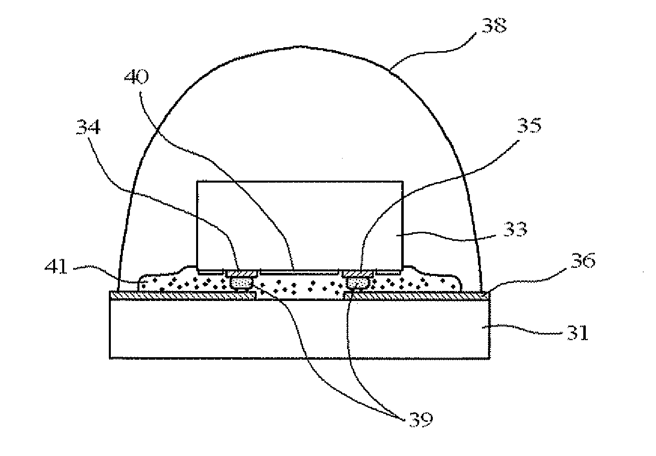
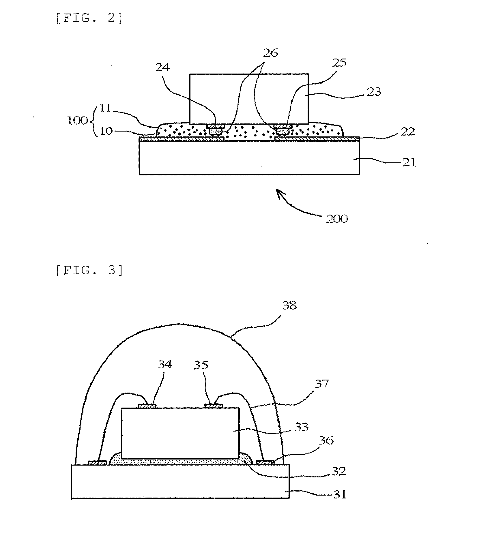
TECHNICAL FIELD[0001]The present invention relates to a light-reflective anisotropic conductive adhesive used for anisotropic conductive connection of a light-emitting element to a wiring board, and also relates to a light-emitting device in which a light-emitting element is mounted on a wiring board with the adhesive.BACKGROUND ART[0002]Light-emitting devices using light-emitting diode (LED) elements are being widely used. An old-type light-emitting device has a structure shown in FIG. 3. More specifically, an LED element 33 is bonded to a substrate 31 with a die-bonding adhesive 32, and a p electrode 34 and an n electrode 35 on the upper surface of the LED element 33 are wire-bonded to connection terminals 36 of the substrate 31 with gold wires 37. The entire LED element 33 is sealed with a transparent molding resin 38. However, in the light-emitting device shown in FIG. 3, light having a wavelength of 400 to 500 nm and emitted upward from the LED element 33 is absorbed by the gol...

Claims


Application Information

Patent Timeline
IPC IPC(8): H01L33/46H01L33/62
CPCH01L33/60C08K5/0025H01L2924/07811H01B3/00H01L2224/73265H01L2224/73204H01L2224/48091H01L2224/32225H01L2224/16225C09J183/06H01L2224/45144C09J9/02H01L33/62H01L33/46H01L2224/48227C08K5/09C08G77/12C08G77/38C08K2003/2241C08K2003/2296H01B1/22H01L2924/00H01L2924/00014C09J183/04C09J11/04H01B1/00H01B1/20H01B5/16
Inventor UMAKOSHI, HIDEAKINAMIKI, HIDETSUGUAOKI, MASAHARUISHIGAMI, AKIRAKANISAWA, SHIYUKI
Owner DEXERIALS CORP
Learn More