Scanning 3D imager

Active Publication Date: 2013-05-02
IEE INT ELECTRONICS & ENG SA
View PDF4 Cites 45 Cited by
  • Summary
  • Abstract
  • Description
  • Claims
  • Application Information

AI Technical Summary

Benefits of technology

[0017]The invention provides a 3D

Problems solved by technology

This analog ToF measurement technique is subject to many measurement errors that require special measures to correct them.
Background light suppression is theoretically possible but proves to be difficult to implement.
This high power light requirement represents a major disadvantage for many applications.
The major disadvantage is the very high power of the IR light source.
Imaging features of such devices were typically limited to scanning one or two planes by using a rotating polygonal mirror.
LADAR instruments, which are mainly used in military applications and in scientific experiments, are traditionally expensive.
Imaging performance is poor and the time required for recording a complete image very long.
The power of the emitted laser light pulse is limited by cost and eye safety rules.
Larger mirrors have a mass versus stiffness conflict.
On the other hand, image quality needs a well-defined mirror surface shape; this means high stiffness, which requires a thick, i.e. heavy, mirror.
This

Method used


Image

  • Scanning 3D imager
  • Scanning 3D imager
  • Scanning 3D imager

Examples


Embodiment Construction

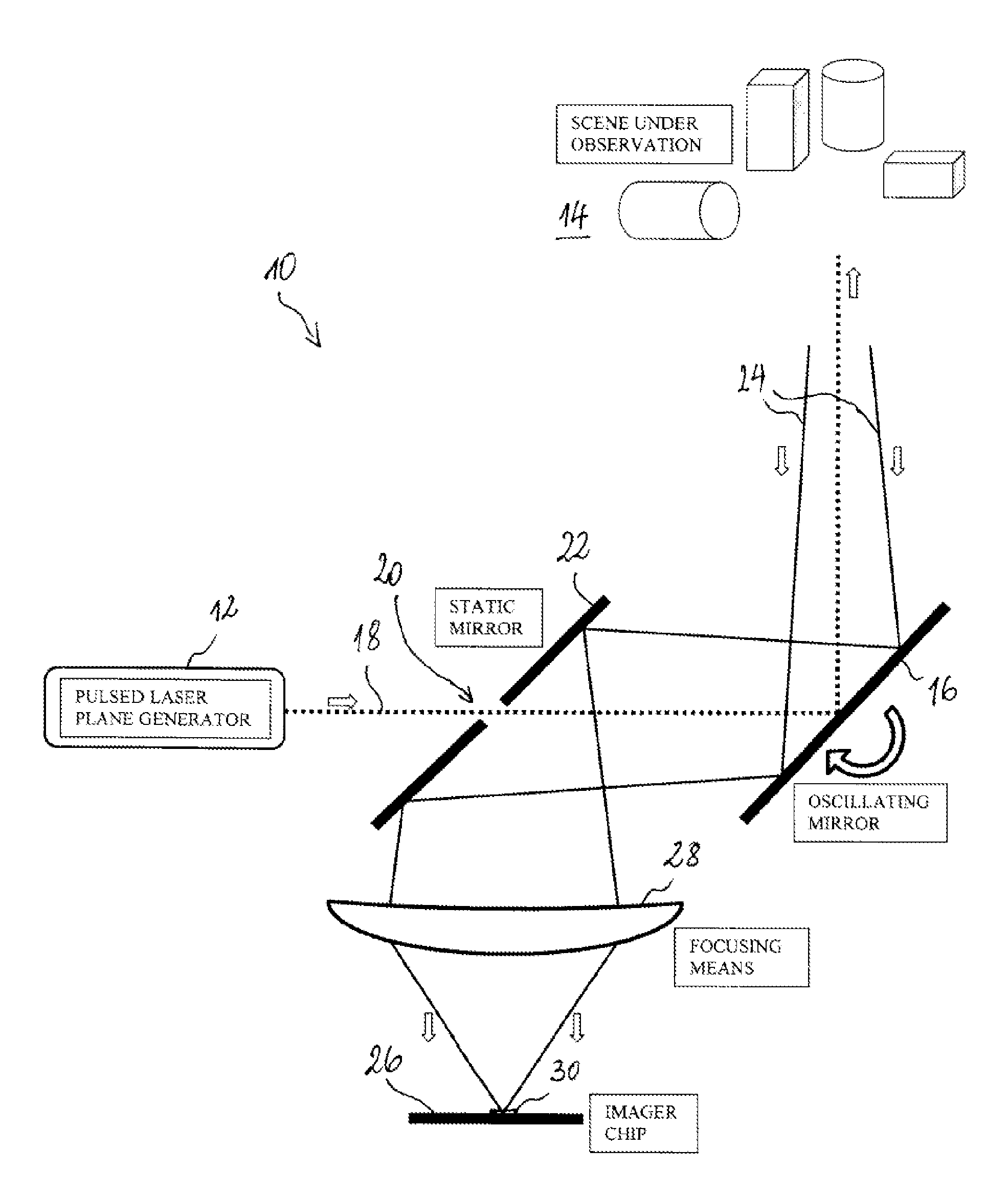
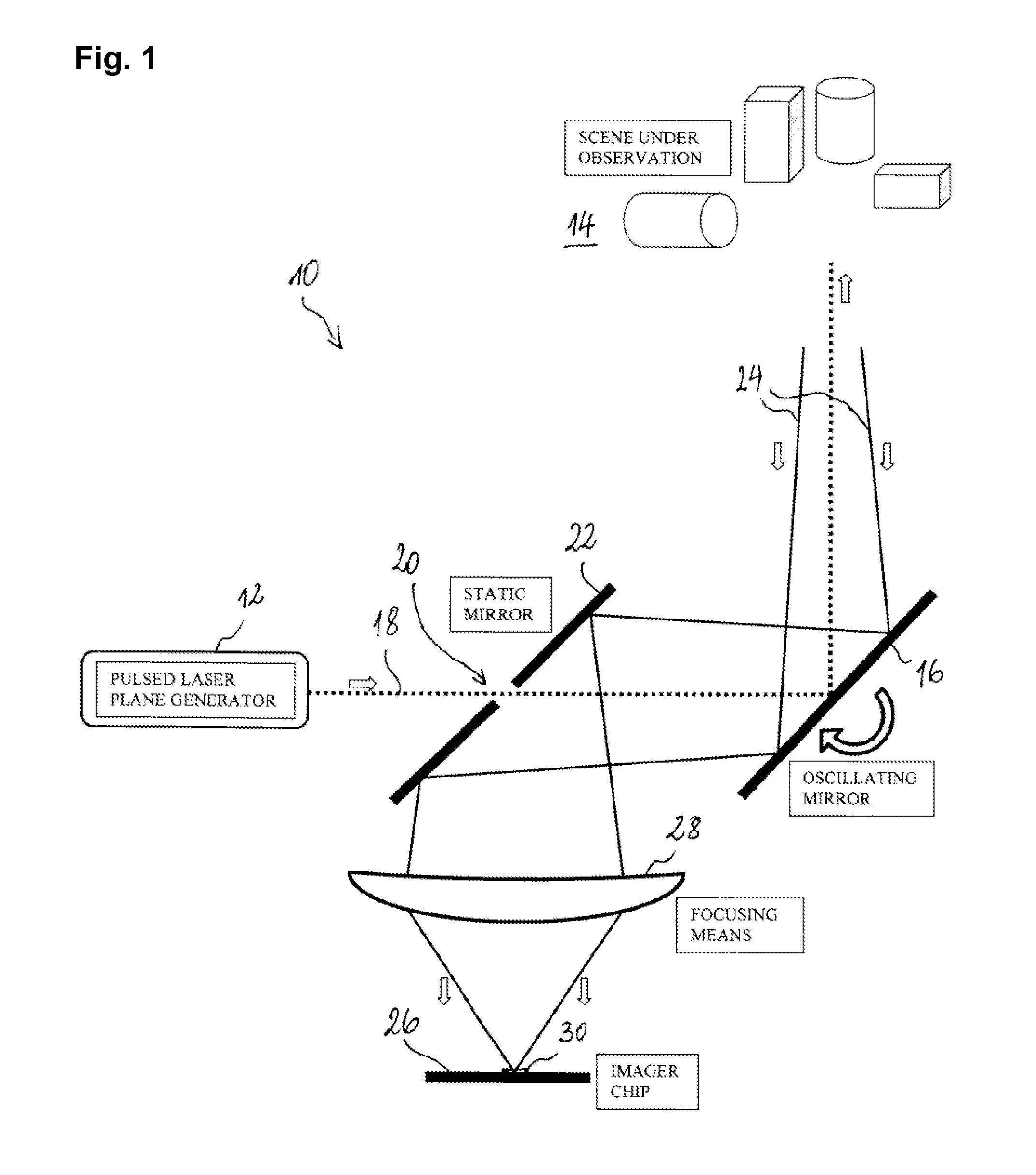
[0038]FIG. 1 shows a scanning 3D imager 10, comprising a pulsed laser source 12 as a light source. The pulsed laser beam is fanned out with a cylindrical lens (not shown) and directed into the scene 14 to be imaged by means of an oscillating scanning mirror 16 arranged in the light path of the laser beam 18. The laser beam thus successively illuminates slices of the scene 16 as it is swept through the scene transversally to the plane in which the laser beam has been fanned out. In FIG. 1, the laser beam 18 is fanned out perpendicular to the plane of the sheet. Between the pulsed laser source 12 and the oscillating mirror, the fan-shaped laser beam passes a slit 20 arranged in a static deflection mirror 22 arranged at 45°, which directs light that is scattered back 24 from the scene 14 onto an imager chip 26. A cylindrical focusing lens 28 focuses oriented in such a way that the illuminated slices of the scene are imaged thereon.

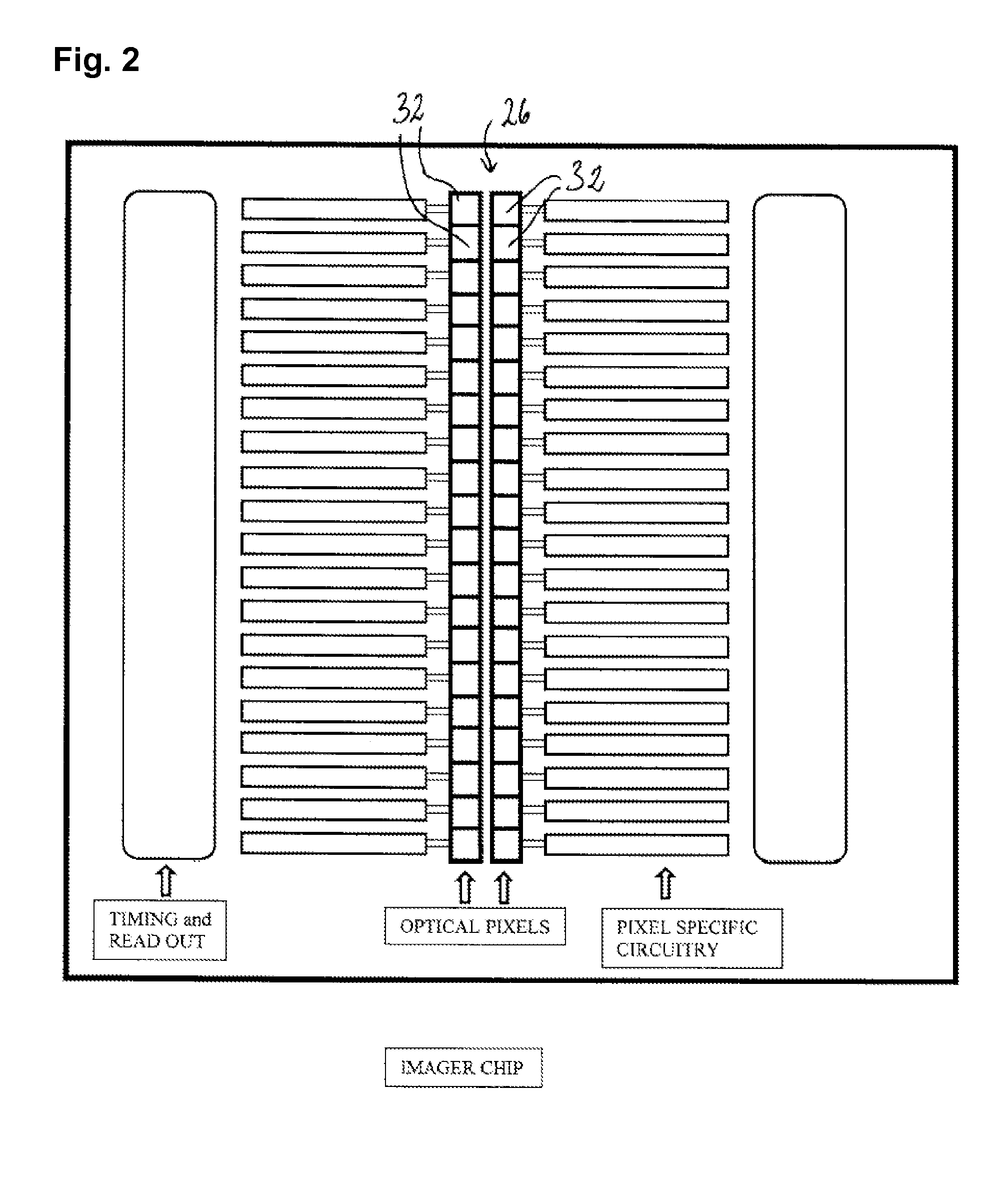
[0039]FIG. 2 schematically shows the imager chip 26 of ...


PUM


Abstract

A scanning 3D imager for recording images of a scene comprises a light source configured to emit a fan-shaped pulsed light beam with linear cross section, a scanning mirror arranged in the light path of the light beam to guide the light beam into the scene and to successively illuminate slices of the scene by sweeping the light beam through the scene transversally to the linear cross section thereof, and an imager chip arranged to receive light from the scene via the scanning mirror, the imager chip comprising an photosensor array disposed in such a way that the illuminated slices of the scene are successively imaged thereon.

Description

TECHNICAL FIELD[0001]The present invention relates to a scanning 3D imager, in particular such an imager that operates according to the time-of-flight (ToF) measurement principle.BRIEF DESCRIPTION OF RELATED ART[0002]Systems for creating a three-dimensional (3D) representation of a given portion of space have a variety of potential applications in many different fields. Examples are automotive sensor technology (e.g. vehicle occupant detection and / or classification), automation technology, or surveillance technology (e.g. plant monitoring, people counting, access control and pedestrian detection), to name only a few.[0003]According to the ToF distance measurement principle, a light signal is emitted into the scene of interest and the time between the emission and the echo-return of the emitted signal is measured. The corresponding distance is proportional to the measured time-of-flight. For the purposes of the present description, the term “light” is to be understood as including vi...

Claims


Application Information

Patent Timeline
IPC IPC(8): H04N13/02G01S7/4863G01S17/89
CPCG01S7/4817G01S7/4863H04N13/0253G02B26/105G01S17/89H04N13/254
Inventor FEDERSPIEL, LAURENT
Owner IEE INT ELECTRONICS & ENG SA
Why Eureka
Try Eureka