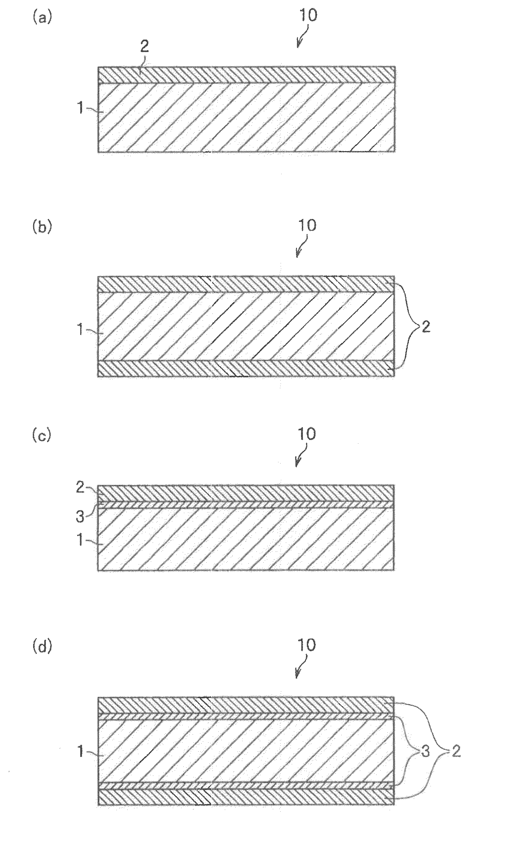
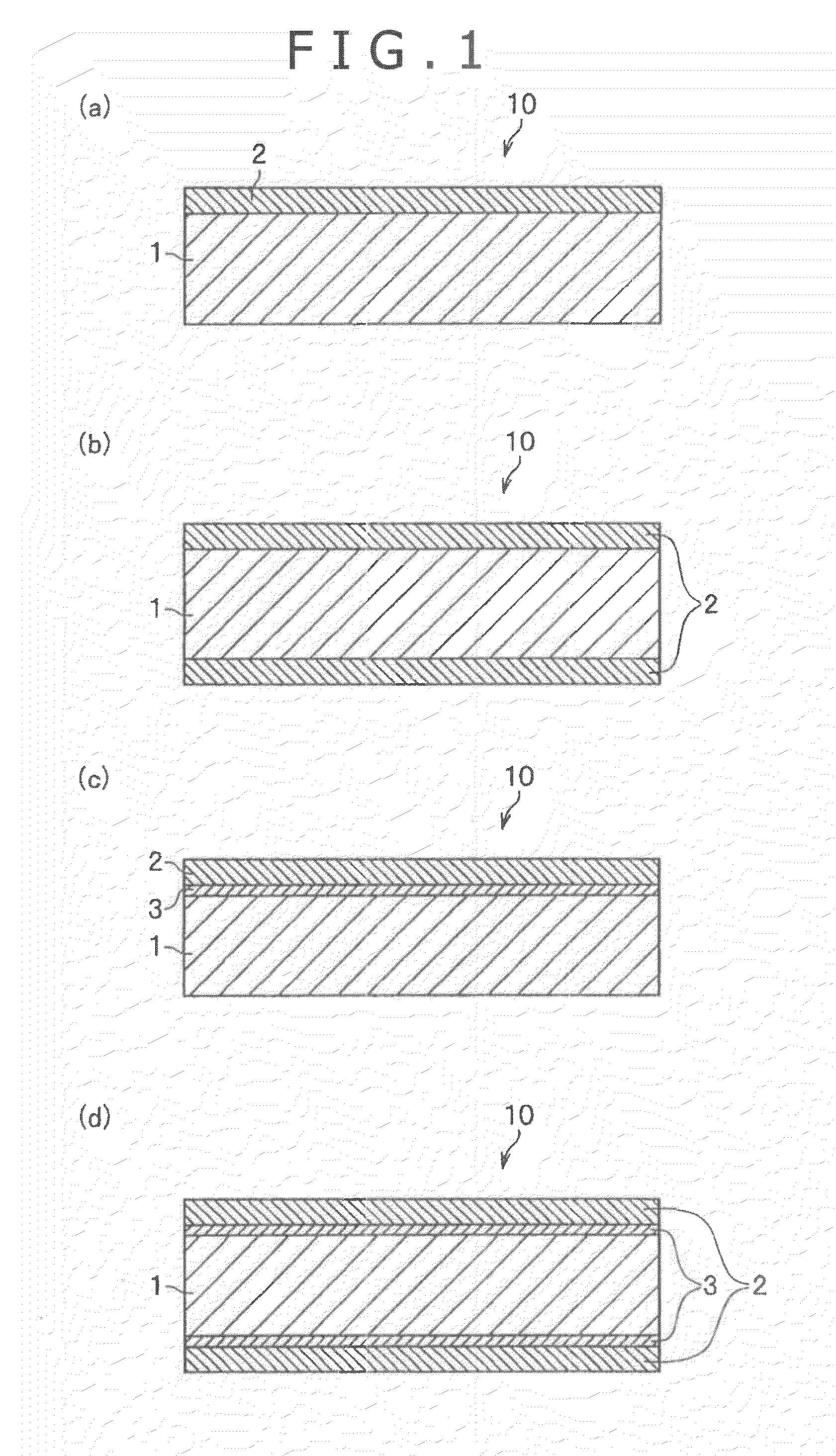
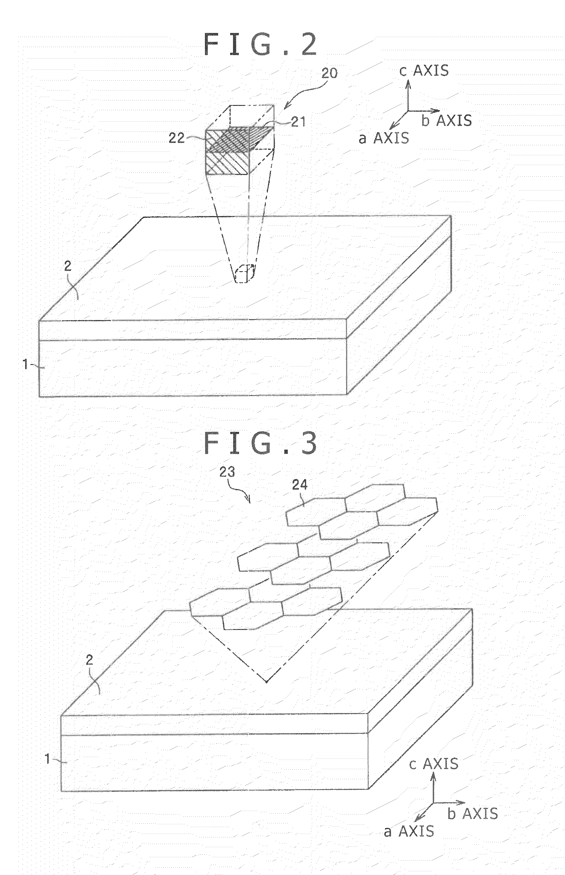
Titanium fuel cell separator
a fuel cell separator and titanium technology, applied in the manufacture of final products, cell components, cell component details, etc., can solve the problems of inferior strength and toughness of separation devices, high cost, and poor conductivity of separation devices, so as to improve conductivity and durability, and have conductivity and durability at certain levels. , the effect of better conductivity
- Summary
- Abstract
- Description
- Claims
- Application Information
AI Technical Summary
Benefits of technology
Problems solved by technology
Method used
Image
Examples
examples
[0082]The titanium fuel cell separator according to the present invention will be illustrated in detail below, with reference to examples satisfying conditions specified in the present invention, and comparative examples not satisfying the conditions.
first experimental example
[0083]Pure titanium of JIS Class 1, which had undergone annealed and picked finish, was used as a substrate. The pure titanium had a chemical composition including oxygen (O) in a content of 450 ppm, iron (Fe) in a content of 250 ppm, and nitrogen (N) in a content of 40 ppm, and further including titanium (Ti) and inevitable impurities. The titanium substrate had a thickness of 0.5 mm. Carbon powders used herein were graphite having an average particle size of 5 μm or 10 μm and four-nines purity; and acetylene black having an average particle size of 50 nm and four-nines purity. The titanium substrate was obtained by subjecting a titanium material subsequently to melting step, casting step, hot rolling step, and cold rolling step according to known procedures.
[0084]The carbon powder was dispersed to a predetermined concentration in a 1 percent by weight aqueous methylcellulose solution to give a slurry. The slurry was applied to both sides of the titanium substra...
second experimental example
[0103]Specimens were prepared by the procedure of First Experimental Example, using a titanium substrate of the same type and same size as with one used in First Experimental Example and using a graphite (graphite having an average particle size of 5 μm and four-nines purity used in Specimens Nos. 11 to 15).
[0104]The resulting specimens were subjected to determination of intermediate layer, measurement of coating mass of carbon, and evaluation of carbon layer adhesion according to the following methods.
[Intermediate Layer Determination]
[0105]A cross section of a specimen surface layer was processed using an ion beam processing instrument (Hitachi Focused Ion Beam System FB-2100) to give a sample, the sample cross section was observed with a transmission electron microscope (TEM: Hitachi Field Emission Analytical Electron Microscope HF-2200) at a 750000-fold magnification, and whether or not titanium carbide was present at the interface between the carbon layer and the titanium subst...
PUM
| Property | Measurement | Unit |
|---|---|---|
| thickness | aaaaa | aaaaa |
| thickness | aaaaa | aaaaa |
| mass | aaaaa | aaaaa |
Abstract
Description
Claims
Application Information
 - R&D
- Intellectual Property
- Life Sciences
- Materials
- Tech Scout
- Unparalleled Data Quality
- Higher Quality Content
- 60% Fewer Hallucinations
Browse by: Latest US Patents, China's latest patents, Technical Efficacy Thesaurus, Application Domain, Technology Topic, Popular Technical Reports.
© 2025 PatSnap. All rights reserved.Legal|Privacy policy|Modern Slavery Act Transparency Statement|Sitemap|About US| Contact US: help@patsnap.com


