Method and apparatus for manufacturing a magnetorheological elastomer

a technology of magnetorheological elastomer and method, which is applied in the field of electromagnetically controlled devices for manufacturing anisotropic magnetorheological elastomers, can solve the problems of reducing the physical properties of the magnet, difficult to separate the magnet, and difficult to obtain a magnetic field strength of 0.5 tesla or more, so as to achieve the effect of reducing the strength of the magnetic field, reducing the difficulty of cip orientation, and reducing the difficulty

Inactive Publication Date: 2013-06-13
HYUNDAI MOTOR CO LTD +1
View PDF4 Cites 10 Cited by
  • Summary
  • Abstract
  • Description
  • Claims
  • Application Information

AI Technical Summary

Benefits of technology

[0012]In one aspect, the invention provides an electromagnetic device that is able to more efficiently induce CIP orientation when a magnetic field is applied as compared to the case where a standard magnet is used. The electromagnetic device of the invention makes it is possible to control the strength of a magnetic field, and to achieve a higher strength of the magnetic field, which has the tremendous advantage of allowing the prevention of bubbles within an MRE test piece, thereby solving the conventional art problem of the re-arrangement or misalignment of oriented CIP within the MRE. This increases the MRE's magnetorheological effect showing a modulus difference before and after magnetic field application.
[0013]An object of the present invention is to provide a novel electromagnetic device for improving a magnetorheological (MR) effect, which shows a modulus difference before and after magnetic field application. It is also an object of the present invention to improve the mechanical properties of an anisotropic MRE, in which the strength of a magnetic field can be adjusted. It is a further object of the present invention to improve the CIP orientation in the resulting MRE.

Problems solved by technology

This method is disadvantageous because it is difficult to separate the magnet, and to mount a test piece due to a high magnetic force of the neodymium magnet.
Furthermore, this method is problematic because it generates bubbles within the MRE test piece, as well as re-arrangement or misalignment of the CIP orientation, thereby reducing physical properties of the MRE.
However, this method suffers from several major disadvantages.
For example, it is difficult to obtain a magnetic field strength of 0.5 Tesla or more.
Also, due to the characteristics of a molding process, the orientation of the CIP is significantly reduced and non-optimal.
Furthermore, as shown in FIG. 3, there this method results in re-arrangement or misalignment of the CIP orientation.
However, the MRE manufacturing mold of the conventional art presents several problems.
For example, the MRE manufacturing mold makes it difficult to separate the neodymium magnet so as to remove the test piece from the MRE manufacturing mold after the molding process due to the very high magnetic force of neodymium magnets.
This represents a significant disadvantage as the presence of such bubbles results in the production of an MRE with significantly reduced, or non-optimal, physical properties.
However, despite the use of magnetic responsive components in all of these manufacturing methods, the problems, enumerated above, which are caused by the use of a magnet in the devices are not overcome.

Method used


Image

  • Method and apparatus for manufacturing a magnetorheological elastomer
  • Method and apparatus for manufacturing a magnetorheological elastomer
  • Method and apparatus for manufacturing a magnetorheological elastomer

Examples


example 1

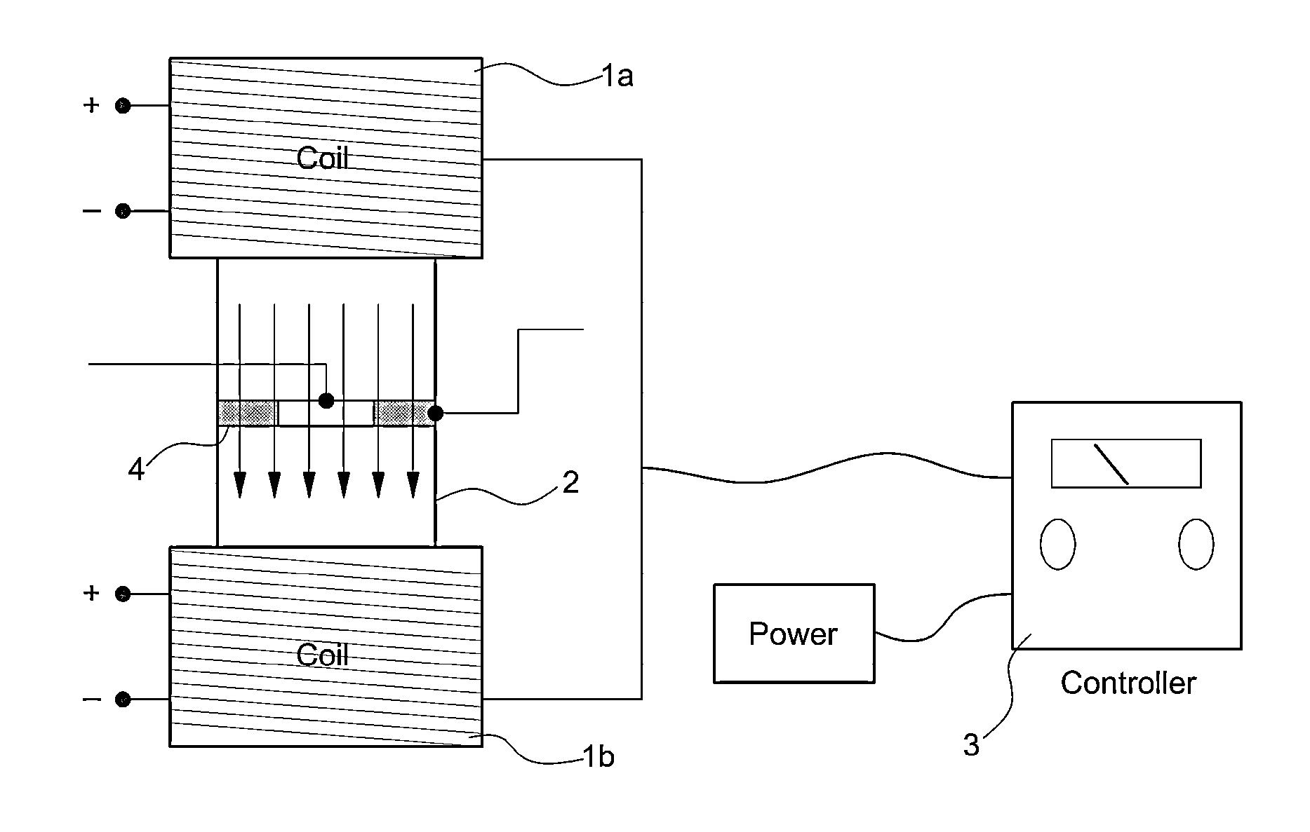
[0066]Natural rubber used as a matrix, various kinds of additives, and CIP were roll-milled to provide a rubber compound. The rubber compound was firstly molded in a hydraulic press (100° C.) for a scorch time or less so as to provide a sheet with a thickness of 2 to 4 mm. Herein, it is important to control the processing condition in such a manner that scorching (that is, curing) of the matrix cannot be proceeded. The first molded product, remaining in the mold, was positioned in an electromagnetic device. Then, under an optimum process condition set in the present invention, that is, at 200 V for 15 min, a second molded product was manufactured by inducing the orientation of CIP. Finally, the second molded product was cured in a hydraulic press (set temperature: 160° C.) for an optimum curing time measured by a rubber rheometer so as to manufacture a final anisotropic MRE.

example 2

[0067]Natural rubber, additives, and CIP were blended through roll-milling in the same manner as described in Example 1. Then, the rubber blend was introduced into a hydraulic press without being applied with a magnetic field through an electromagnetic device, and cured for a final curing time measured by a rubber rheometer so as to manufacture an isotropic MRE having CIP particles randomly dispersed therein.

example 3

[0068]Magnetic responsive particles (CIP) were coated with a silane coupling agent by the following steps. First, an aqueous solution (Ethanol / Water=95 / 5) was added with acetic acid so as to provide a solution of pH 5, and then a silane coupling agent (A1130) was added in an amount of 2 vol % thereto, followed by stifling for 5 minutes so as to induce sufficient hydrolysis of the silane coupling agent.

[0069]Then, CIP was added thereto, followed by stirring for 3 minutes. The resulting mixture was dried at room temperature so that a silane-coated CIP was produced. In the silane-coated CIP, the condensation between a silanol group and CIP was achieved, and there remains a site reactable with natural rubber.


PUM

PropertyMeasurementUnit
thicknessaaaaaaaaaa
thicknessaaaaaaaaaa
temperatureaaaaaaaaaa

Abstract

Disclosed is a method and electromagnetic device for manufacturing an anisotropic magneto-rheological elastomer (MRE) with an improved magneto-rheological effect. The electromagnetic device includes upper and lower electromagnets, and a test piece located therebetween. The upper and lower electromagnets are configured to apply a magnetic field of variable strength, which may be controlled by current applied from a power controller, to the test piece in a desired direction or orientation. More specifically, the device is designed in such a manner that carbonyl iron powder (CIP) (magnetic-responsive particles) dispersed in a magneto-rheological elastomer using natural rubber as a matrix can be oriented in the application direction of the magnetic field. A MRE produced by the method and electromagnetic device of the invention prevents formation of bubbles within a test piece, thereby improving the arrangement/orientation of CIP with the matrix.

Description

CROSS-REFERENCE TO RELATED APPLICATION[0001]This application claims under 35 U.S.C. §119(a) the benefit of Korean Patent Application No. 10-2011-0133989, filed on Dec. 13, 2011, the entire contents of which are incorporated herein by reference.BACKGROUND[0002](a) Technical Field[0003]The present invention relates to an electromagnetic device for manufacturing an anisotropic Magnetorheological Elastomer (MRE) with improved magnetorheological effect. More particularly, the present invention relates to an electromagnetic device for manufacturing an anisotropic MRE, in which carbonyl iron powder (CIP) (magnetic-responsive particles) dispersed in a magnetorheological elastomer using natural rubber as a matrix can be oriented in the direction of an applied magnetic field.[0004](b) Background Art[0005]According to the conventional art, an MRE is manufactured using a neodymium magnet and an MRE manufacturing mold having the neodymium magnet inserted therein as shown in FIGS. 1 and 2. This m...

Claims


Application Information

Patent Timeline
Patent Type & Authority Applications(United States)
IPC IPC(8): B29B13/08C08L7/00B29C35/02
CPCH01F1/28H01F7/20H01F1/447F16F9/535H01F41/028
Inventor KIM, MIN SOOYANG, KYUNG-MOLEE, SEONG HOONCHUNG, KYUNG-HOLEE, JOO-HWAN
Owner HYUNDAI MOTOR CO LTD
Why Eureka
Try Eureka