[0018]Another additional aspect of the present disclosure describes a device further comprising one or more polarizers and one or more analyzers disposed between the material layer and the one or more measurement units. This configuration allows for the performance of
ellipsometry on the material layer in order to provide an alternative method for determining the thickness and the rate of change of the thickness of the material layer during processing.
[0021]Aspects of the present disclosure include a device that is built on a production substrate. The production substrate may be divided into one or more active device dice and one or more monitor dice. The active device dice may have functioning devices being built on them. The monitor dice may have material
layer thickness monitors built on them. The presence of the material
layer thickness monitors may provide additional information about the processing conditions that the functioning devices were exposed to, thereby allowing for better
process control and a higher yield.
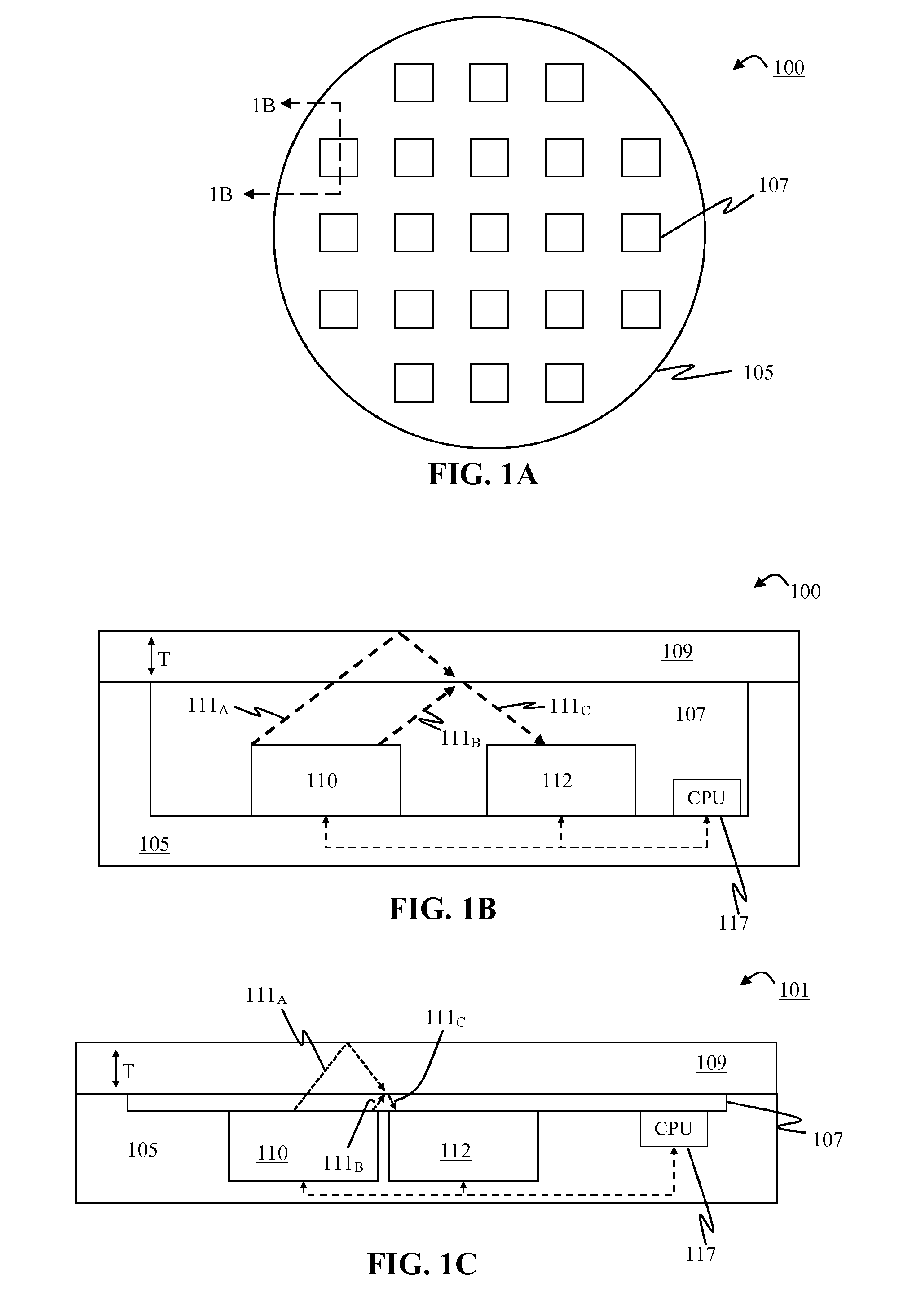
[0023]Returning to FIG. 1A, the cavities 107 may be distributed across the surface of the substrate 105. This arrangement provides multiple locations across the surface for measurements to be taken. In many material processing operations, such as but not limited to CVD, the deposition or
etching rates may vary across the surface of the device 100. As such, the use of multiple cavities allows for enhanced
data acquisition and the ability to more precisely define how the processing conditions of a given tool will affect device 100. The figures used in the present disclosure depict a
single measurement unit in each cavity, but the disclosure should not be so limited. By way of example, there may be a plurality of measurement units in each cavity 107. The cavities 107 in FIG. 1B are arranged in a grid-like pattern, but it should be noted that this is just one of the many possible arrangements. By way of example, and not by way of limitation, the cavities 107 may be preferentially formed in locations where there is typically a high variation in the deposition or etch rates. Also, the number of cavities 107 is also variable. Increasing the number of cavities 107 allows for inclusion of more measurement units, and therefore may provide a more complete characterization of the processing operation. Alternatively coarser measurements may be made when fewer cavities 107 are used. According to aspects of the present disclosure a cavity 107 may also be formed in a production
wafer (i.e., a substrate that is being processed in order to fabricate functioning devices). The production substrate may be divided into one or more active device dice and one or more monitor dice. The active device dice may have functioning devices being built on them. The monitor dice may have a cavity 107 with a
light source 110 and a photodetector 112 formed in the cavity. The presence of the measurement unit in the production substrate may provide additional information about the processing conditions that the functioning devices were exposed to, thereby allowing for better
process control and a higher yield.
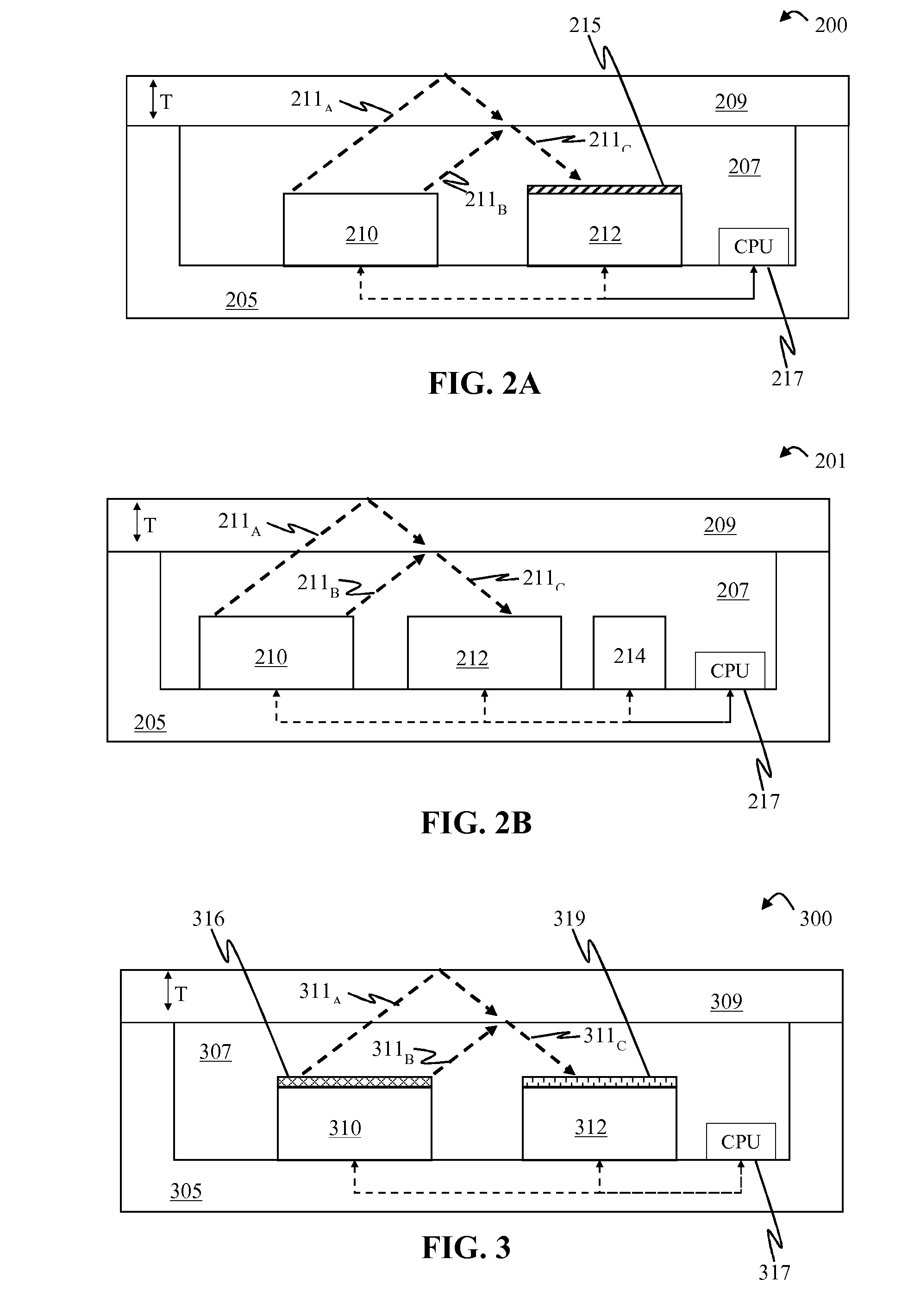
[0027]In a processing chamber, the sensor apparatus 200 may be exposed to light or other
electromagnetic radiation from sources other than the light source 210 in a cavity 207 of a substrate 205. For example,
optical radiation will be present in processes such as
plasma etching and CVD. In order to prevent these additional sources of
optical radiation from interfering with the analysis of the interference pattern of the measured light 211C resulting from interference of first portion 211A and second portion 211B of light from the light source, the light source 210 should have a
narrow bandwidth in order to provide
high contrast between the desired interference
signal and
noise. Light sources 210 such as LEDs and lasers have bandwidths that are sufficiently narrow to allow for
high contrast. The contrast may also be improved by utilizing a photodetector 212 that is configured to detect only a
narrow bandwidth of wavelengths. Additionally, as shown in FIG. 2A an
optical filter215 may also be used. The filter 215 ensures that only
optical radiation of a predetermined that falls within a predetermined bandwidth will be detected by the photodetector 212. The filter may be placed between the photodetector and the material layer, such that substantially all of the light detected by the photodetector 212 passes through the filter 215.
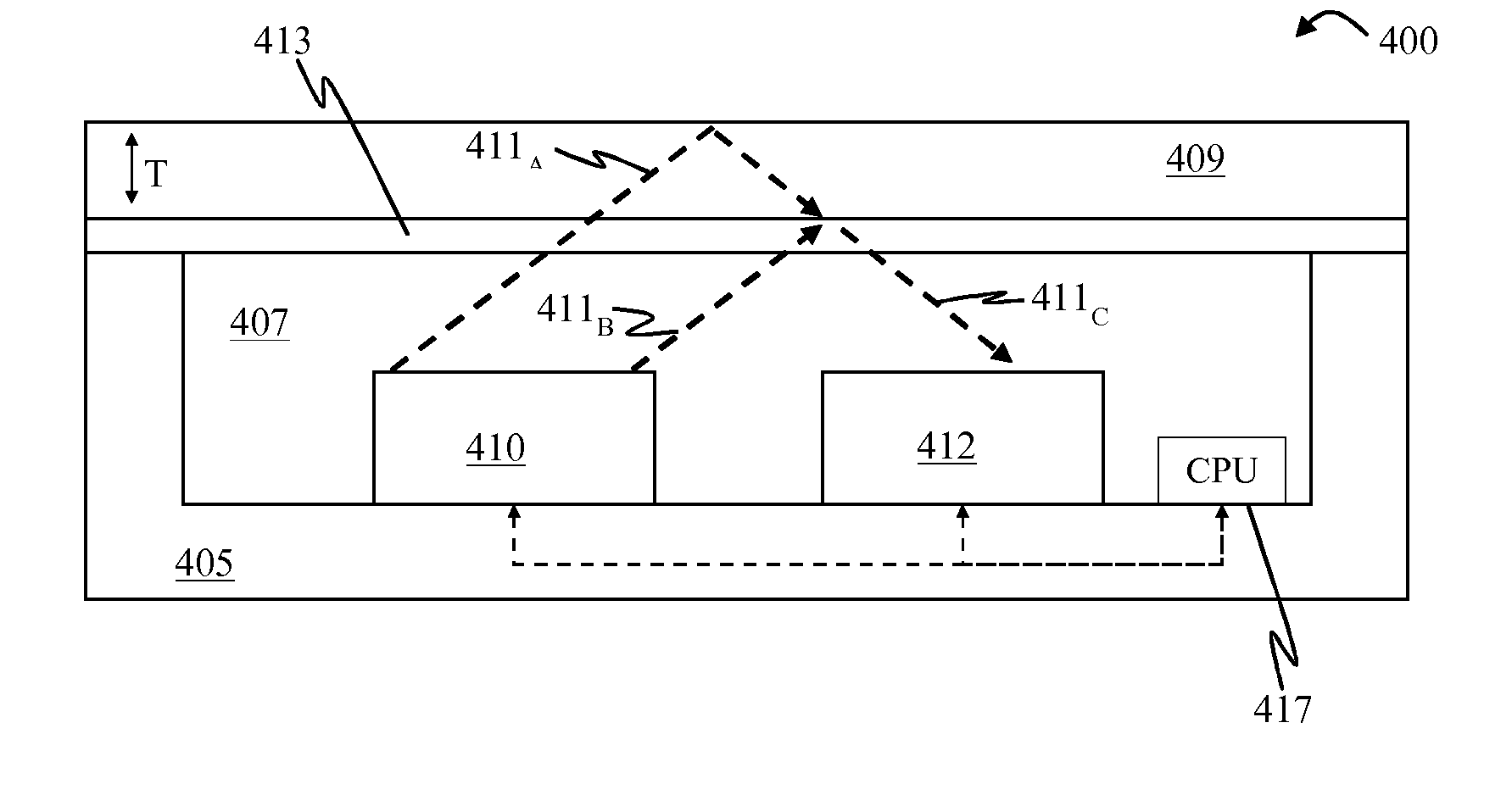
[0034]The cover 413 also provides a
solid surface spanning over the one or more cavities 407. Due to this, a bare cover 413 (i.e., a cover that lacks any portion of the material layer 409 already formed on the top surface) may be used to measure the rate of change of thickness at the
initiation of a
deposition process. This may provide additional information that would otherwise not be available without the use of the cover, because when no cover 413 is used, a sufficiently thick portion of the material layer 409 must already be spanning the cavity 407 in order to provide a surface on which additional material may be deposited. Additionally, the use of a cover 413 allows for multiple uses of the sensor apparatus 400 when the cover 413 is made from a material that is not etched away with the same etching processes used to remove the material layer 409. In situations where the material layer 409 is etched away during the processing step, a new material layer may be grown on the cover 413 after the processing step has been completed. In situations where the material layer 409 is added during the processing step, such as a material
deposition process, then the material layer 409 may be etched away with an etching process after the deposition process has been completed.

