
Cost-Efficient Treatment Of Fluoride Waste

Active Publication Date: 2013-06-27
TOWER SEMICONDUCTOR
View PDF7 Cites 6 Cited by
  • Summary
  • Abstract
  • Description
  • Claims
  • Application Information

AI Technical Summary

Benefits of technology

The present invention provides a system for treating wastewater that contains fluoride using the waste produced by a regeneration cycle in an ion exchange water softener. This treatment method is efficient and cost-effective. The waste produced by the regeneration cycle contains calcium and magnesium salts that react with fluoride present in the wastewater. By adjusting the pH of the reaction tank, the system can efficiently clarify the output, settle the resulting sludge, and dewater it. This invention helps save money and simplifies the dosing system by eliminating the need for expensive calcium salts and simplifying the measurement process for fluoride concentration.

Problems solved by technology

The cost of chemicals (e.g., calcium salt) is a significant part of total cost of waste treatment.
Precise and complicated control of the chemical dosing is typically required due to variations in fluoride concentration in the wastewater feed.
This undesirably results in relatively complicated and costly fluoride treatment systems.
As a result, the dose of the regeneration process brine cannot be predetermined based on the fluoride concentration of the influent fluoride-containing wastewater.

Method used


Image

  • Cost-Efficient Treatment Of Fluoride Waste
  • Cost-Efficient Treatment Of Fluoride Waste
  • Cost-Efficient Treatment Of Fluoride Waste

Examples


first embodiment

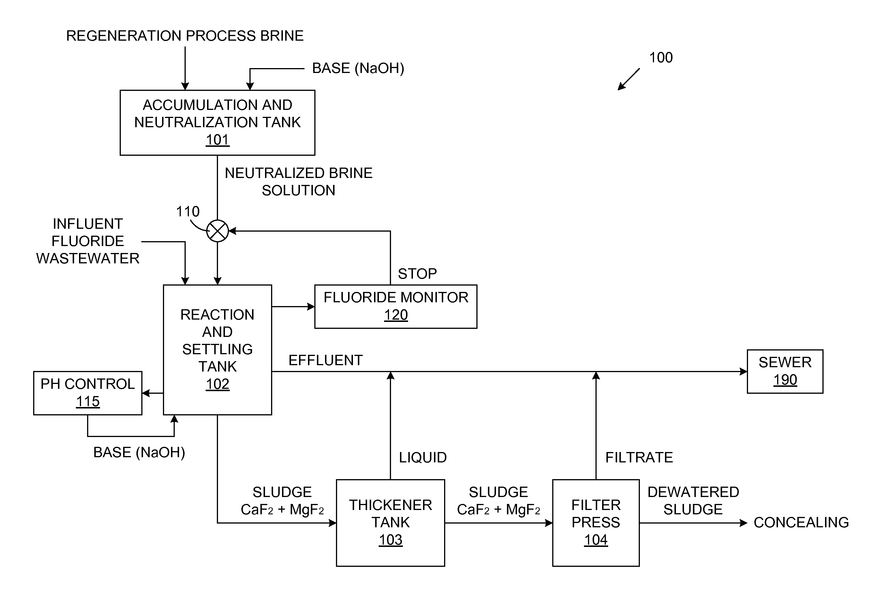
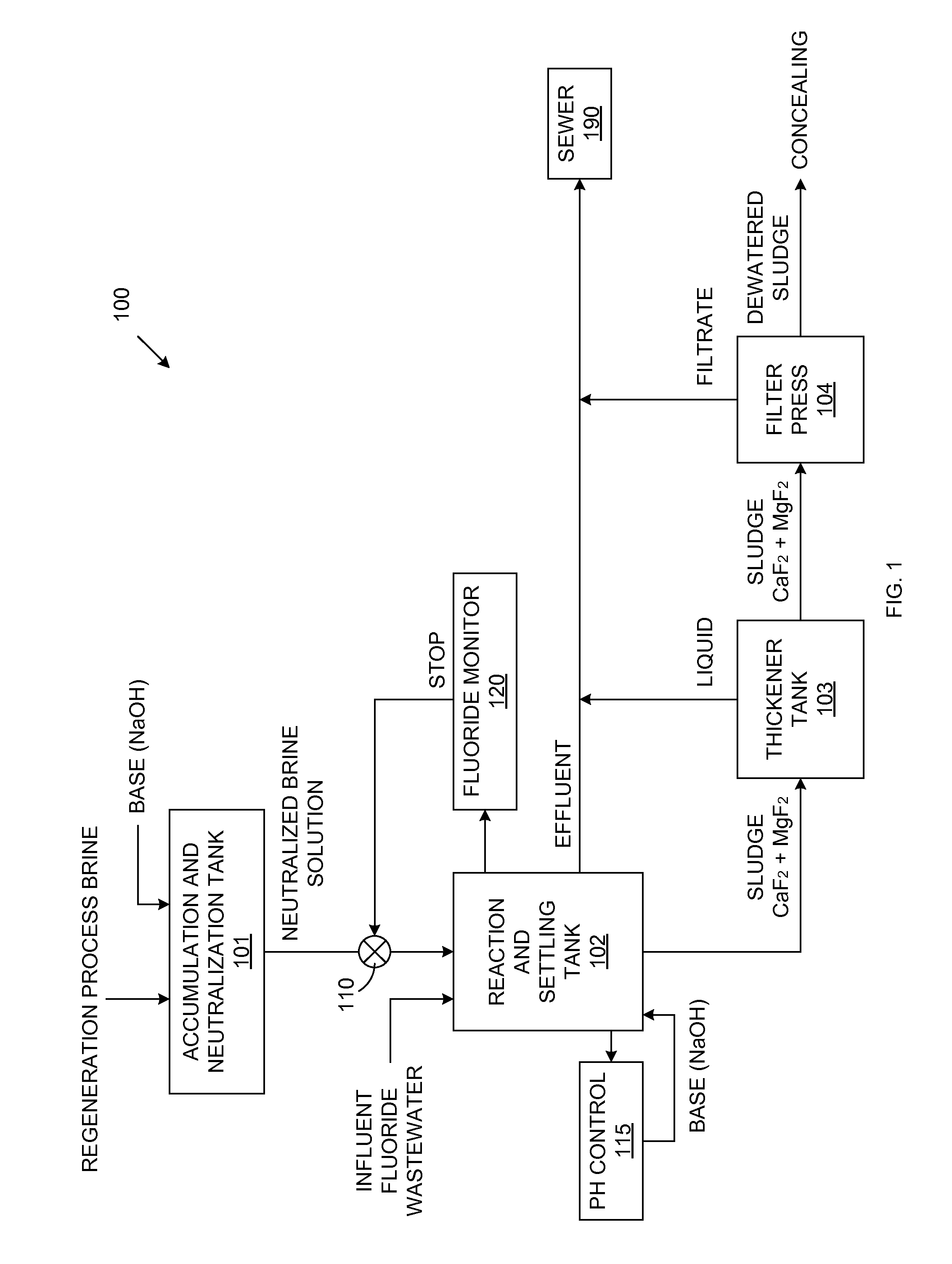
[0023]FIG. 1 is a block diagram of a fluoride wastewater treatment system 100 in accordance with the present invention. As illustrated in FIG. 1, regeneration process brine (obtained from the regeneration process of an ion exchange softener used for pretreatment of raw water in a UPW plant of a semiconductor fabrication facility) is added to accumulation and neutralization tank 101. Hydrochloric acid, which is inherently present in the regeneration process brine, causes this brine to have a relatively low pH. The regeneration process brine is neutralized with a basic agent to create a neutralized brine solution having a pH of up to about 7. In accordance with one embodiment, the basic agent added to tank 101 is NaOH. However, it is understood that other basic agents can be used in other embodiments.

[0024]Influent fluoride wastewater is pumped into reaction and settling tank 102. In the described embodiment, this fluoride wastewater contains about 30,000 ppm of fluoride, mostly in so...

second embodiment

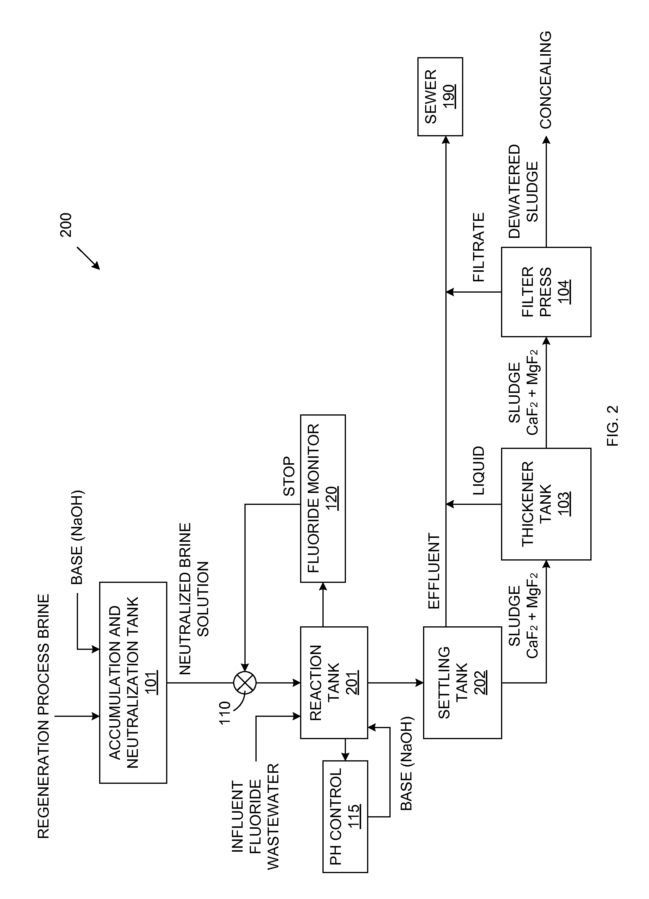
[0028]FIG. 2 is a block diagram of a fluoride wastewater treatment system 200 in accordance with the present invention. Because system 200 is similar to system 100, similar elements in FIGS. 1 and 2 are labeled with similar reference numbers. System 200 replaces the reaction and settling tank 102 of system 100 with two separate tanks. Thus, system 200 includes reaction tank 201 and settling tank 202. Processing proceeds in the manner described above in connection with FIG. 1, wherein the influent fluoride-containing wastewater is pumped into reaction tank 201, and the neutralized regeneration process brine is then added to the reaction tank 201, while a mixer is controlled to mix the contents of reaction tank 201. During this process, pH controller 115 monitors the pH level of the mixture in the reaction tank 201. Again, pH controller 115 adds a basic agent (e.g., NaOH) to the reaction 201, as necessary, to maintain a pH greater than 9.

[0029]During the above-described process, the f...

third embodiment

[0030]FIG. 3 is a block diagram of a fluoride wastewater treatment system 300 in accordance with the present invention. Because system 300 is similar to systems 100 and 200, similar elements in FIGS. 1, 2 and 3 are labeled with similar reference numbers. System 300 eliminates the thickener tank 103 and the settling tank 202 from system 200. Processing proceeds in the manner described above in connection with FIG. 2, wherein the suspension of CaF2 and MgF2 from the reaction tank 201 is transferred directly to the filter press 104. The filtrate from the filter press 104 is safely disposed into the sewer system 190, while the dewatered sludge from the filter press 104 is properly disposed.

[0031]If the available capacity of the filter press 104 is limited, coagulants and / or flocculants can be applied to the suspension to facilitate the separation of the sludge from the filtrate. Eliminating the settling tank 202 and the thickener tank 103 from system 300 advantageously allows system 300...


PUM

PropertyMeasurementUnit
Basicityaaaaaaaaaa
Concentrationaaaaaaaaaa
Contentaaaaaaaaaa

Abstract

A method and system for processing fluoride-containing wastewater includes treating the wastewater with brine (waste) created by the regeneration process implemented by in ion exchanging water softener. The brine, which is typically disposed of, contains both calcium and magnesium salts, in varying concentrations and ratios. The regeneration process brine is added to the fluoride-containing wastewater within a reaction tank, and the fluoride ion concentration is monitored. When the fluoride ion concentration falls below a predetermined level (e.g., 15 ppm), the flow of regeneration process brine is stopped. A pH controller monitors the pH within the reaction tank, and adds a basic agent to ensure that the pH remains above a predetermined level (e.g., pH>9). The pH control results in a clear effluent, and a sludge having a high settling rate and a high dewater ability.

Description

FIELD OF THE INVENTION [0001]The present invention relates to methods for efficiently treating fluoride-containing waste.RELATED ART[0002]Fluoride found in wastewater generated by semiconductor fabrication plants (or other industrial plants) must be removed before the wastewater may be safely disposed. In many cases fluoride-containing wastewater is treated by a calcium salt addition process, followed by precipitation of calcium fluoride and further dewatering by filter press. The cost of chemicals (e.g., calcium salt) is a significant part of total cost of waste treatment. Precise and complicated control of the chemical dosing is typically required due to variations in fluoride concentration in the wastewater feed.[0003]Application of adding calcium salt for the removal of fluoride is known in waste treatment. For example, a system and method for removing fluoride from wastewater by the addition of calcium salts is described by G. A. Krulik, et al., in U.S. Pat. No. 6,645,385. Krul...

Claims


Application Information

Patent Timeline
IPC IPC(8): C02F1/58B01D36/04C02F1/68C02F1/52C02F1/66C02F11/121
CPCC02F1/66C02F2101/14C02F11/121C02F1/5236
Inventor LURIE, MICHAELSHTAL, MILAN
Owner TOWER SEMICONDUCTOR
Learn More