
Methods and Apparatuses for Water Purification

a technology of water purification and water filter, applied in lighting and heating apparatus, evaporator regulation/control, separation process, etc., can solve the problems of contaminated water, lack of clean drinking water, disease, suffering and ultimately death, etc., and achieve low cost, energy saving, and low energy methods

Active Publication Date: 2013-07-11
CHANG HUEI MENG
View PDF8 Cites 28 Cited by
  • Summary
  • Abstract
  • Description
  • Claims
  • Application Information

AI Technical Summary

Benefits of technology

This patent is about a filtration apparatus that has multiple chambers for evaporation and condensation. This arrangement increases the surface area for heat exchange, which helps to capture more latent heat at high production rates. The invention also includes a feature that allows the system to monitor its performance and automatically adjust itself to optimal levels.

Problems solved by technology

Lack of clean drinking water is still the primary cause for disease, suffering and ultimately death in many parts of the world.
Even where water is available to the public, often times the available water is contaminated by chemicals used in agriculture, e.g., by industrial contamination or by sewage seeping into the water supply.
Additionally, areas in close proximity to an ocean have a water source of high salinity, and consequently not suitable for drinking.
Water that is centrally treated is also not safe in many parts of the world as positive pressure is not maintained at all times in the distribution network for the water.
Leaks in the distribution network can cause contamination of the water in this system.
Furthermore, the multiple points where the water is stored after an initial treatment, e.g., storage tanks, lack any kind of continuous supervision and sanitation.
In particular, storage tanks are not cleaned regularly, thereby becoming sources of contamination and having an ecosystem of their own with all sorts of insects, animals, bacterial growth, and algal growth.
However, in rural areas, this is not possible, nor desired, since transportation of the bottled water to the end users is often difficult and since the indiscriminate use of plastics for the bottled water has caused a disposal and recycling nightmare.
Once these consumables are not replaced due to neglect or non-availability, the quality of the output water (otherwise referred to as product water) from these systems is severely degraded and in many cases becomes worse than the actual input water due to internal contamination.
The HDH systems fare even worse in this respect with a specific energy cost ranging from 150 kWh / ton to more than 400 kWh / ton.
However, thermal distillation generally produces highly purified water with a TDS (total dissolved solid) level well below 1 ppm (part per million), while it would be impractical for RO plants to produce water purity of less than 20 ppm or so.
RO is also unable to filter out light weight dissolved chemical molecules if their sizes are comparable to the average pore size of the RO membrane.
RO is also far more prone to fouling, scaling, and plugging of the membrane, and rapid oxidation can easily destroy the membrane if it is directly exposed to air.
While all water purification techniques require pretreatments or pre-filtering to reduce the probability of fouling and to ensure proper operation of the main purification process, RO typically requires more pretreatments to protect its membranes from failures, and the standard half-life of an RO membrane is about two years, hence the costs of its consumables represent a large part of its total operational cost.
Although MVC thermal distillation technology has largely caught up to RO in terms of specific energy cost, its initial capital cost is still far higher than comparable RO technologies owing to its much lower packing density.
However, the extremely low specific energy efficiencies of these systems have been the main obstacles to their wide acceptance.
Another drawback is that existing distillation technologies are far too costly to implement since these technologies use a large amount of energy to convert water to steam before recondensing the saturated gases and since these technologies are typically built with expensive stainless steel or other costly metals.
One of the major disadvantages of the existing distillation techniques is the requirement to employ high strength materials for the containment and heat exchange walls.
Another disadvantage of the existing distillation techniques is the comparatively low packing density, or surface to volume ratio of the heat exchange surfaces.
Still another disadvantage for some of the existing distillation techniques is the lack of direct 2-phase to 2-phase heat exchange.
Unfortunately, due to the design of the prior art, several inefficiencies are apparent.
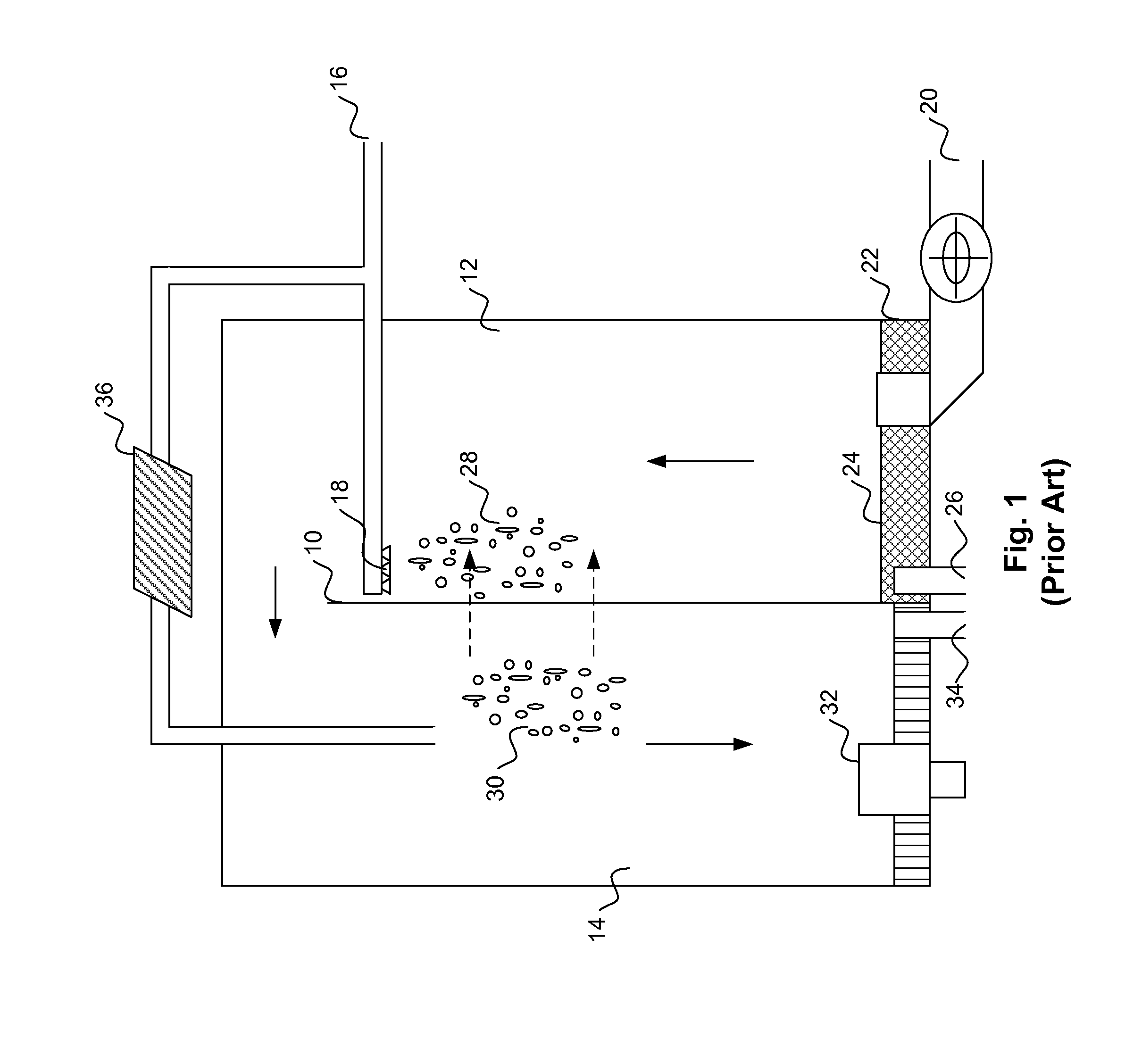
First, the vertical heat exchange wall 10 is not fully utilized since most of the latent heat transfer is inefficiently transferred from gases in the condensation chamber 14 to other gases in the evaporation chamber 12.
The low affinity (wettability) of the plastic heat exchange surface to liquid makes it hard for the condensing liquid on the condenser side to form filmwise or dropwise condensation, and to form filmwise evaporation on the evaporator side; this drastically reduces the heat transfer efficiency and lowers the fraction of the latent heat that can be recovered.
Lower latent heat exchange performance increases internal entropy production.
As will be clear below, any increase in internal entropy production decreases total system efficiency and / or reduces water production rate.
In addition, the open loop process does not reuse the sensible heat that still remains within the non-condensed gasses that are routed via the air outlet 32 from being reused.
Although rerouting the non-condensed gases to the bottom of the evaporation chamber can recoup some of the waste heat, such a process is inherently inefficient owing to the large temperature difference between the non-condensed gas and the feed water.
Another main drawback of said prior art is its use of hot steam injection to provide the needed heat input for evaporation.
Such entropy ejection leads to increased energy consumption which decreases the overall system efficiency and / or production rate.

Method used


Image

  • Methods and Apparatuses for Water Purification
  • Methods and Apparatuses for Water Purification
  • Methods and Apparatuses for Water Purification

Examples


Embodiment Construction

[0065]In the following detailed description of the embodiments, reference is made to the accompanying drawings, which form a part hereof, and in which is shown by way of illustration of specific embodiments in which the present invention may be practiced.

[0066]The below description described the invention in relation to purifying dirty water. However, it is understood that the present invention can be applied for purifying a host of other liquids, including saline water, contaminated water, or other liquids.

[0067]The present invention overcomes many deficiencies of the current art by using the minimum entropy production principle to maximize latent heat exchange efficiencies and by increasing the packing density of the heat exchange surfaces. Additionally, the present invention provides real-time adaptive control of the system operation to continuously retune the system parameters as well as switching to alternate energy source to maintain low operational costs.

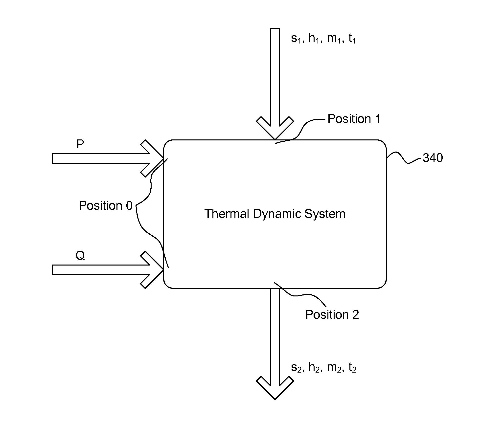
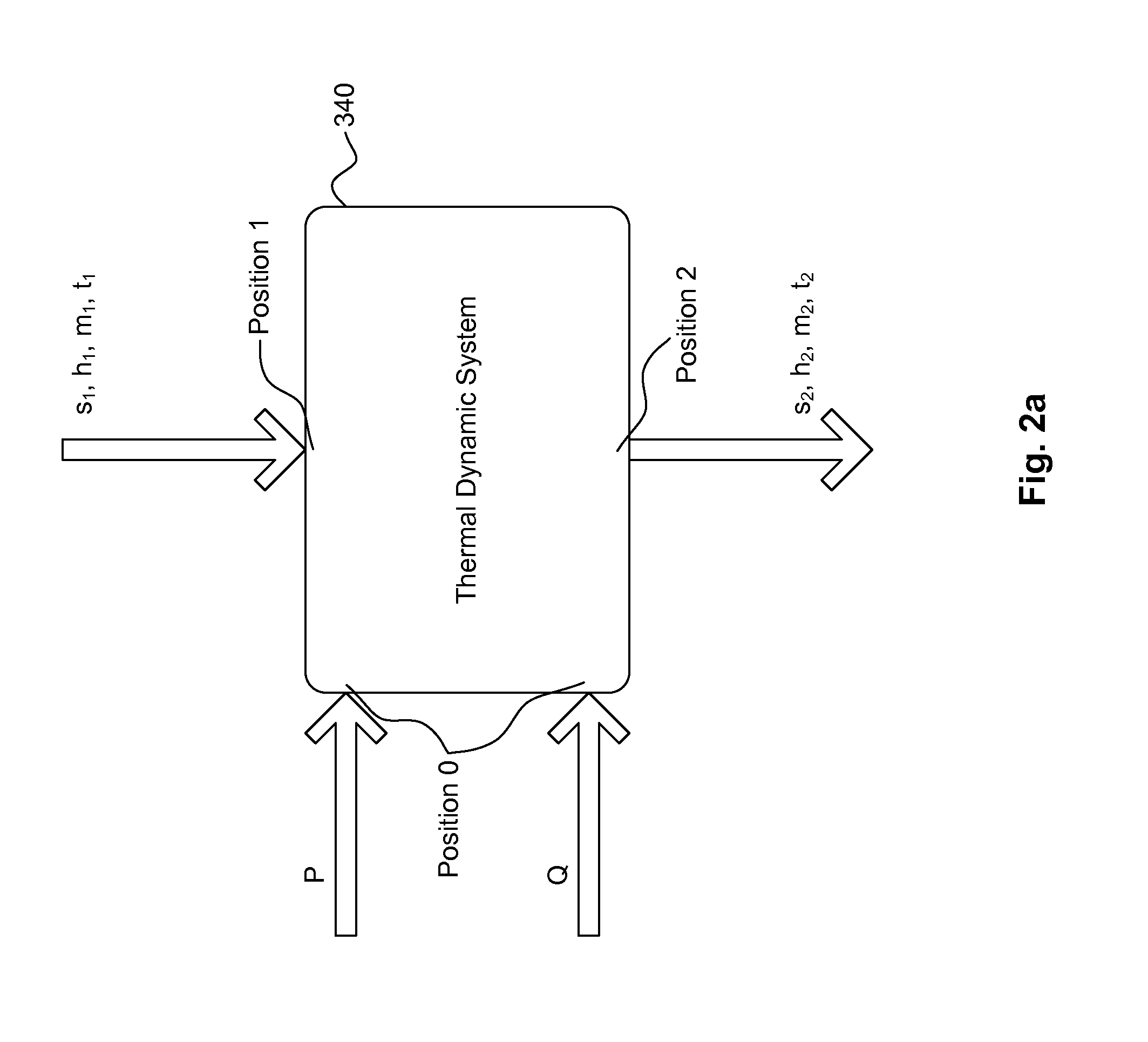
[0068]FIG. 2a illustr...


PUM

PropertyMeasurementUnit
Pressureaaaaaaaaaa
Concentrationaaaaaaaaaa
Latent heataaaaaaaaaa

Abstract

An apparatus for generating purified liquid from an input liquid, comprises, an evaporation chamber, wherein the evaporation chamber is flooded with the input liquid; and a condensation chamber having channels, wherein the channels are disposed in the input liquid, wherein liquid-saturated gases are generated from the input liquid in the evaporation chamber, wherein the liquid-saturated gases are guided into a first end of the channels, and wherein the purified liquid is outputted at a second end of the channels.

Description

CROSS REFERENCE[0001]This application claims priority from a provisional patent application entitled “Method and Apparatus for Water Purification” filed on Jan. 11, 2012, having an Application No. 61 / 585,293, and from a provisional patent application entitled “Methods and Apparatuses for Water Purification” filed on Nov. 16, 2012, having an Application No. 61 / 727,661. Said applications are incorporated herein by reference.FIELD OF INVENTION[0002]This invention generally relates to methods and apparatuses for water purification, and, in particular, to methods and apparatuses for water purification using humidification-dehumidification (“HDH”).BACKGROUND[0003]Lack of clean drinking water is still the primary cause for disease, suffering and ultimately death in many parts of the world. Even where water is available to the public, often times the available water is contaminated by chemicals used in agriculture, e.g., by industrial contamination or by sewage seeping into the water supply...

Claims


Application Information

Patent Timeline
IPC IPC(8): C02F1/04
CPCB01D1/04B01D1/22B01D1/24C02F1/043B01D1/305B01D5/006B01D1/28B01D1/00B01D1/0082B01D1/30C02F1/04C02F1/52Y02W10/33Y02W10/37B01D1/14B01D1/2818F28D1/0246B01D1/284
Inventor LEE, YEE CHUNRAJU, NARAYAN D.CHANG, HUEI MENGTAN, AH BENG
Owner CHANG HUEI MENG
Learn More