Method for controlling a laser processing operation by means of a reinforcement learning agent and laser material processing head using the same

a laser processing and reinforcement learning technology, applied in the direction of program control, total factory control, instruments, etc., can solve the problems of suspension of assembly lines, loss of quality, and user's need to spend a great deal of cost and effort on trials before a laser processing system, so as to increase the flexibility of the production system, improve the quality and efficiency, and maintain the effect of quality

Active Publication Date: 2013-07-11
PRECITEC GMBH +1
View PDF0 Cites 32 Cited by
  • Summary
  • Abstract
  • Description
  • Claims
  • Application Information

AI Technical Summary

Benefits of technology

[0023]The present invention should demonstrate reliable detection of a lack of fusion. A successful closed-loop control method for the future should not only be able to adapt the laser power to speed alterations, it should also be applicable to at least two different processing tasks. In other words, the agent should adjust the laser power to speed changes in order to maintain a similar energy per unit length level within a set of experiments for similar welding or cutting results. In addition, in order to investigate the cognitive capabilities of the system, it should be able to learn from human experts, as well as show reasonable behavior and continued learning from feedback in an unsupervised mode within experiments.
[0024]Thus, it is a main object of the present invention to take advantage of cognitive capabilities in order to increase a production system in flexibility, quality, and efficiency. This can be further separated in f

Problems solved by technology

Furthermore, due to a computer's superior skills in data analysis, agents may be able to manage complex production tasks that are challenging even for human experts.
However, users must expend a great deal of cost and effort on trials before a laser processing system can run.
Even if all process parameters remain untouched, slight differences in workpiece, workload, alignment, room temperature, or optical properties may result in a loss of quality and, in the worst case, a suspension of the assembly line.
For example, five 8 kW fiber lasers with a wall plug efficiency of 30% integrated in an assembly line in Germany operating 253 days a year, 18 hours a day, create operational electricity costs of over US$50,000 annually.
Taking only a factor of six, this would add up to operational electricity costs of US$300,000 and over 100 metric tons of annual CO2 emission.
Because this process involves high effort and cost, manufacturers often declare the parameter sets to be classified.
However, even if every attempt is made to keep all process parameters constant, slight changes and nonlinear behavior can result in poor cutting quality or welding defects.
Problems in cutting edge quality include, for instance, dross, roughness, or parallelism of edges.
A welding seam may have undesired surface irregularities, including breaks, holes, material ejections, the formation of spatters, cracks, pores, seam width variation, and many more.
On top of these, there may also be welding errors, such as an undesired degree of welding depth or insufficient connection, which often cannot be observed without destroying the welding seam.
The latter may expand and lead to a complete lack of fusion.
A lack of fusion involves a gap between the partners that should have been joined.
As mentioned above, detecting false friends is a difficult monitoring task because the weld seam may appear defect-free from the outside at the location of a lack of fusion.
On the contrary, this method seems to require costly equipment and the configuration of fixed measurement positions.
However, it is hardly possible to co

Method used


Image

  • Method for controlling a laser processing operation by means of a reinforcement learning agent and laser material processing head using the same
  • Method for controlling a laser processing operation by means of a reinforcement learning agent and laser material processing head using the same
  • Method for controlling a laser processing operation by means of a reinforcement learning agent and laser material processing head using the same

Examples


first embodiment

[0156]In the following, the present invention regarding monitoring gaps with a lack of fusion in laser welding should be described.

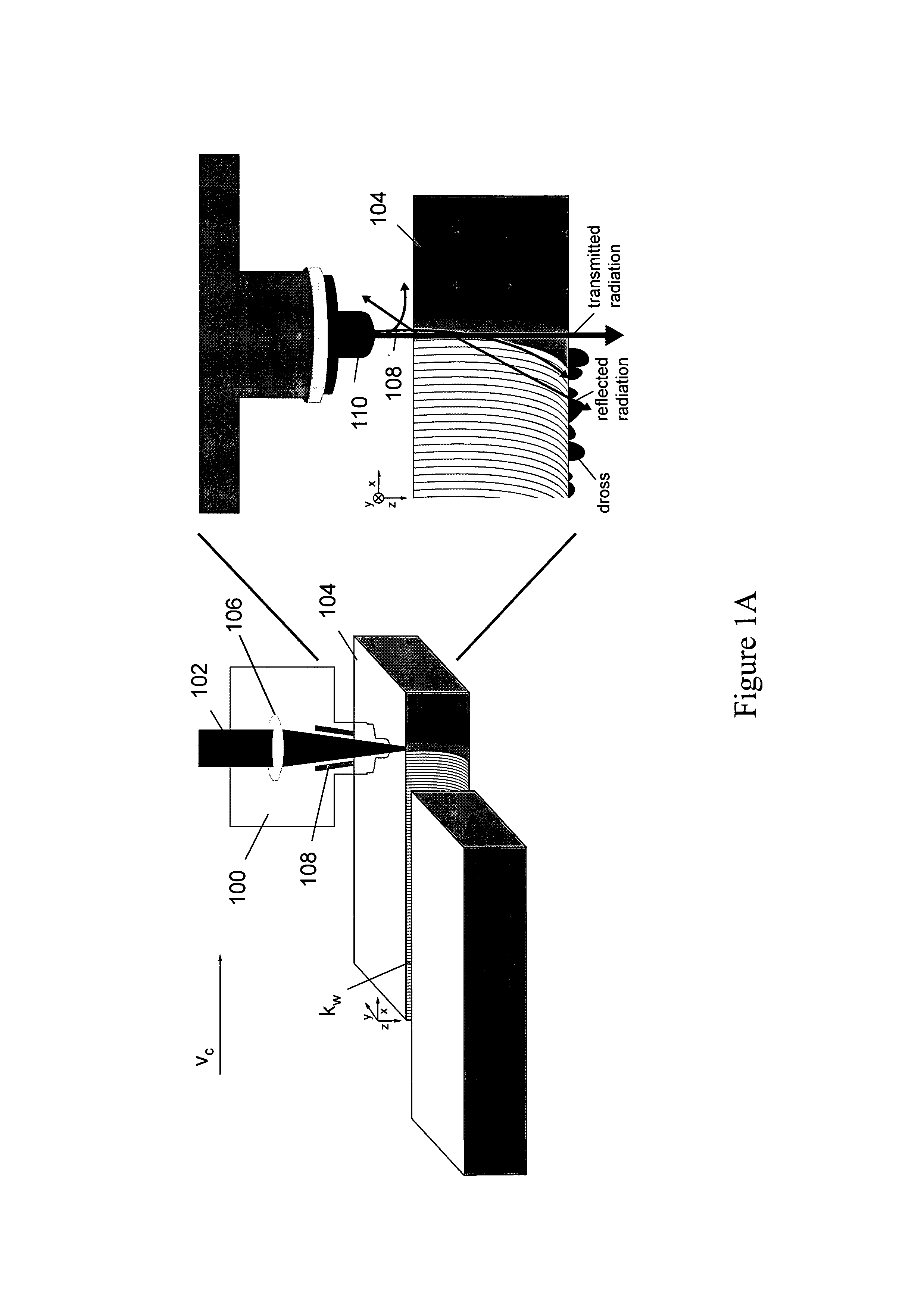
[0157]Current industrial solutions may successfully monitor many defects that occur during joining processes. However, detecting insufficient connection or a lack of fusion because of gaps between two sheets is challenging. This defect often occurs if the gap between the two sheets is too large. Even if the laser beam penetrates through the top and bottom layers of the two sheets, the gap may still be too large for a successful joint, and a complete lack of fusion or false friend can occur. Because the beam has penetrated the top and bottom sheets, the defect is often not visible when inspecting the workpiece after processing.

[0158]Car manufacturers increasingly integrate zinc-coated alloys. When welding zinc-coated workpieces, it is advantageous to leave a specific gap between the two work-pieces which will be joined. This gap allows any zinc vapor to d...

second embodiment

[0172]In the following, the present invention regarding agent control of laser cutting should be described.

[0173]The agent of a second embodiment of the present invention requires at least one training workpiece with some laser power variation, in this case from 1,500 W to 50 W. The training workpiece is processed at 3.0 m / min, as shown in FIG. 8. A human expert teaches the cutting control agent to keep the cutting kerf stable at 0.4 mm by indicating the corresponding region on the training workpiece. The kerf width varies during cutting with alterations in laser power or processing velocity. Once the agent has trained itself, it will test its cognitive capabilities by processing at different velocity levels. Furthermore, the agent has to transfer the learned knowledge to unknown situations, such as processing different materials or layers of multiple sheets.

[0174]The cutting control agent of the present invention applied throughout all the experiments has trained itself with a stai...

third embodiment

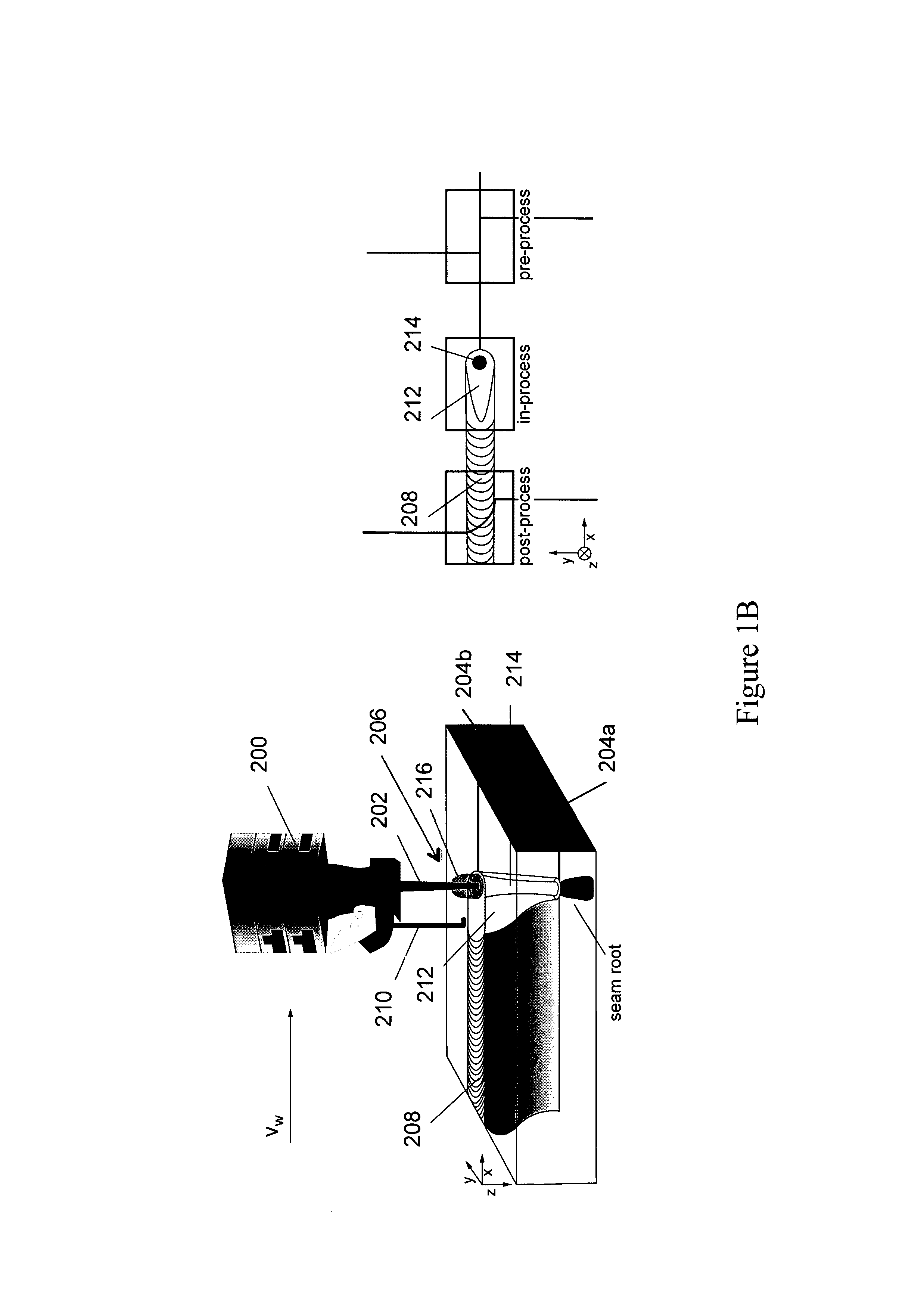
[0182]In the following, a third embodiment related to agent control of laser welding will be described.

[0183]It is a common aim in industrial welding to join two parts with maximal connection, yet to avoid excessive penetration without any weld root convexity or concavity on the obscured side of the workpiece surface. A root convexity or concavity occurs when the laser beam actually exits the workpiece on the bottom side, also known as full penetration weld. This leaves a noticeable convex or concave trace, which restricts a following paint job because the weld seam root would still be evident. As another manufacturing example, with pipe welding this type of imperfection may cause undesired behavior in the fluid flow that can cause erosion or corrosion issues. If the laser power could be controlled in terms of the penetration depth, it may be maintained at the desired level, thus creating maximal connection without the beam leaving the workpiece. Due to the nonlinearity of the weldi...


PUM

PropertyMeasurementUnit
Temperatureaaaaaaaaaa
Wavelengthaaaaaaaaaa

Abstract

The present invention relates to a method for controlling a processing operation of a workpiece by means of a Reinforcement Learning (RL) agent unit, comprising the steps of: (a) observing an interaction zone in the workpiece by means of at least one radiation sensor to generate at least one sensor signal st, wherein the workpiece is processed using an actuator having an initial actuator value at; (b) determining a basis function Φ(st) from the set of sensor signals st; (c) determining a reward function rt giving the probability of good results of the processing operation; (d) choosing a next actuator value at+1 on the basis of a policy π depending on the reward function rt and the basis function Φ(st); and (e) repeating the steps (a) to (d) for further time points to perform a RL controlled processing operation.

Description

[0001]The present invention relates to a method for controlling a laser processing operation by means of a Reinforcement Learning Agent and laser material processing head using the same.[0002]In industrial nations with high labor and living costs, it is important to increase automation in manufacturing in order to retain a competitive edge. Furthermore, there is an ongoing trend from mass production toward increased flexibility in product variation while maintaining high output volumes. Cognitive capabilities for production machines may improve with flexibility and automation to contribute to a Cognitive Factory of the future. Artificial software agents; systems with cognitive capabilities, subsequently just agents, may help to tailor products individually and to deliver them on a large scale. Furthermore, due to a computer's superior skills in data analysis, agents may be able to manage complex production tasks that are challenging even for human experts. A possible test scenario f...

Claims


Application Information

Patent Timeline
IPC IPC(8): G05B13/02
CPCB23K1/0056G06T7/0004B23K26/1429B23K26/20B23K26/3206B23K26/3293B23K26/34B23K28/02B23K2201/34B23K2203/02G05B19/4083G05B2219/35085G06K9/6247G06K9/6248G05B13/0265G05B13/0285B23K26/032B23K26/32B23K26/26B23K2103/08B23K26/348B23K2101/34B23K2103/02B23K2103/50G06N3/006G06N20/10G06N3/08G06N7/02G05B19/41875Y02P80/40Y02P90/02G06V10/7715G06N7/01G06F18/2135G06F18/21355B23K26/322
Inventor WERSBORG, INGO STORK GENANNTGARCEA, ADRIAN
Owner PRECITEC GMBH
Why Eureka
Try Eureka