Light emitting body

a technology of light-emitting bodies and carbon phosphors, which is applied in the field of light-emitting bodies, can solve the problems of short emission lifetime of carbon phosphors available by conventional methods, and achieve the effects of short emission lifetime, low emission efficiency and emission lifetim

Inactive Publication Date: 2013-07-18
TOYOTA CENT RES & DEV LAB INC
View PDF6 Cites 10 Cited by
  • Summary
  • Abstract
  • Description
  • Claims
  • Application Information

AI Technical Summary

Benefits of technology

[0189]Non-patent Documents 1 to 3 describe phosphors using, as a base, a graphene synthesized by various processes. As described in Non-patent Document 3, however, conventional phosphors have a very short emission lifetime. In addition, conventional phosphors have low emission efficiency.
[0190]On the other hand, the emission lifetime shows a marked increase when a base material containing a graphene structure is covered with a covering material, which is presumed to occur because of the following reasons:
[0191](1) when the surface of a base material is covered with a covering material having polarity, rotational motion or vibrational motion of the functional group in the covering material enhances the spin-orbit interaction of the graphene structure, resulting in occurrence of intersystem crossing to a triplet state and elongation of the relaxation time of excited electrons.
[0192](2) when the surface of a base material is covered with a covering material having polarity, a hydrogen bond is formed between the covering material and the base material. This hydrogen bond suppresses quenching due to a reaction between a triplet state of the graphene structure and dissolved oxygen, leading to elongation of an emission lifetime.
[0193]Moreover, nitrogen introduced into the graphene structure enhances the emission efficiency further, which is presumed to occur because of the following reason.
[0194]Described specifically, by dispersing graphite oxide and / or graphene oxide in water and heating the resulting dispersion at a predetermined temperature, delamination of graphite oxide and reduction in size, into a nanosize, of sheet-like graphene oxide obtained by delamination occur. At the same time, a reduction reaction of the oxygen-containing functional group (for example, an epoxide group) bound to the graphite oxide or graphene oxide occurs, leading to an increase in the concentration of sp2 clusters serving as an emission center.

Problems solved by technology

Carbon phosphors available by the conventional methods, however, have a markedly short emission lifetime as described in Non-patent Document 3.

Method used


Image

  • Light emitting body
  • Light emitting body

Examples


example 1

1. Preparation of Phosphor Dispersion

[0209]Graphite oxide (0.1 g) was dispersed in 5 mL of a 0.2 mol / l aqueous urea solution. The aqueous solution thus obtained was heated at 150° C. for 10 hours in a hermetically sealed container. After heating, the solution was washed sufficiently to separate a nitrogen-containing graphene structure.

[0210]Next, 10 mg of polyacrylic acid (covering material) was dissolved in 5 mL of an aqueous dispersion having 0.1 mg of the nitrogen-containing graphene structure dispersed therein. The solution thus obtained was dried to yield a nitrogen-containing graphene structure / polyacrylic acid composite.

2. Test Method

[2.1. Emission Spectrum]

[0211]Emission spectrum of a light emitting body was measured using a spectrofluorometer (“FP-6500”, trade name; product of JASCO).

[2.2. Emission Efficiency]

[0212]Emission efficiency was measured using an absolute photo-luminescence quantum yield measurement system (“C9920-02”, trade name; product of Hamamatsu Photonics).

[...

example 2

1. Preparation of Sample

[0215]In a similar manner to Example 1 except for the use of carboxymethyl cellulose as the covering material, a nitrogen-containing graphene structure / carboxymethyl cellulose composite was obtained.

2. Test Method

[0216]Under similar conditions to those in Example 1, emission spectrum, emission efficiency, and emission lifetime were measured.

3. Results

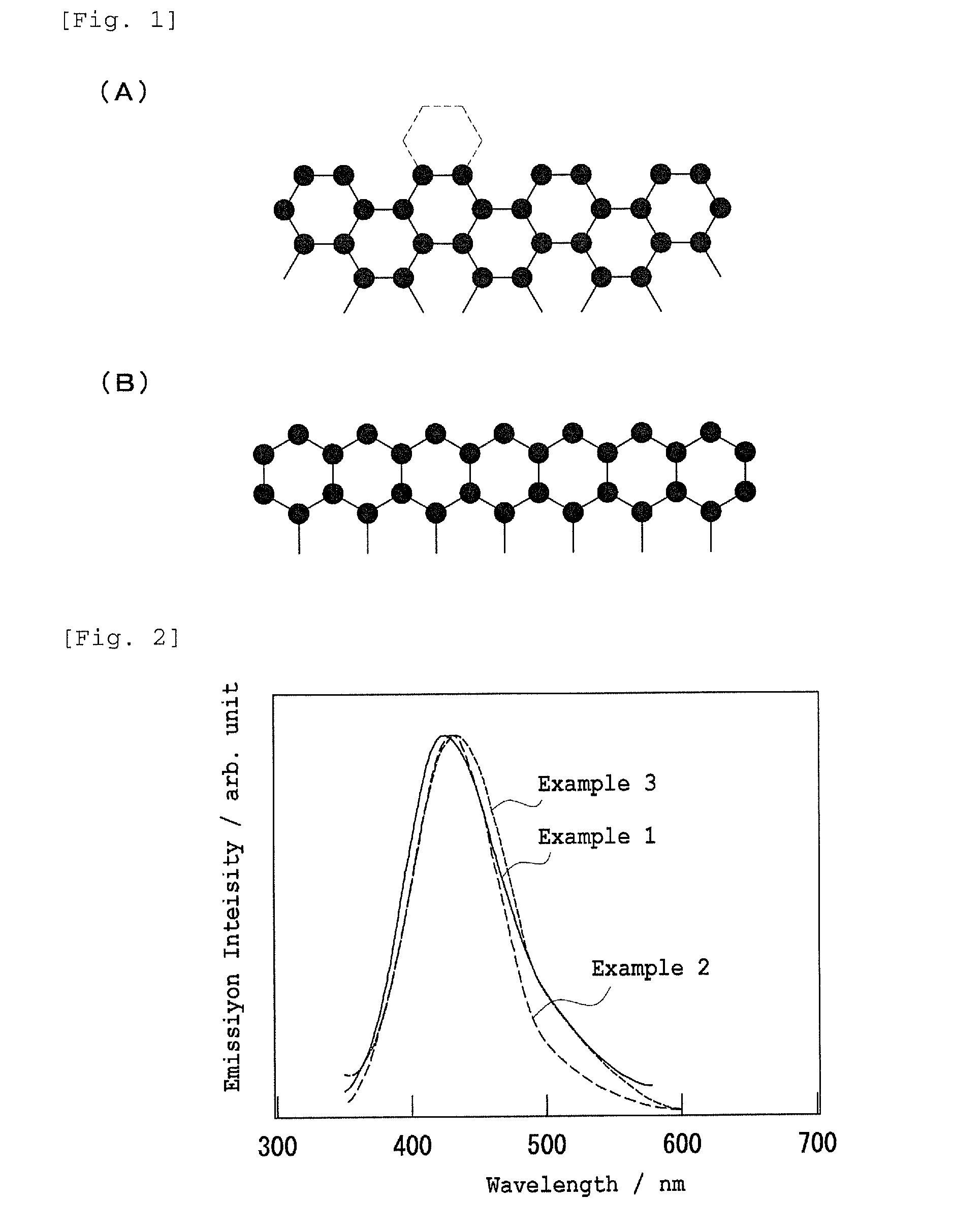
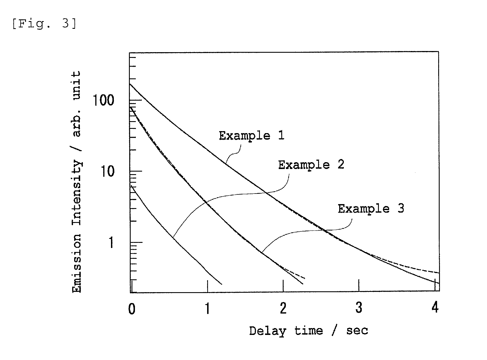
[0217]Results are shown in FIG. 2, FIG. 3, and Table 1. The light emitting body obtained in Example 2 had a peak position of the spectrum at 433 nm and the half width of the peak was 90 nm. In addition, the light emitting body had emission efficiency of 21%, which was markedly higher compared with Non-patent Document 1. It had an emission lifetime of 0.47 second, revealing that it had a very long emission lifetime.

example 3

1. Preparation of Sample

[0218]In a similar manner to Example 1 except for the use of polyvinyl alcohol as the covering material, a nitrogen-containing graphene structure / polyvinyl alcohol composite was obtained.

2. Test Method

[0219]Under similar conditions to Example 1, emission spectrum, emission efficiency, and emission lifetime were measured.

3. Results

[0220]The results are shown in FIG. 2, FIG. 3, and Table 1. The light emitting body obtained in Example 3 had a peak position of the spectrum at 430 nm and the half width of the peak was 78 nm. In addition, it had emission efficiency of 23%, which was markedly higher compared with Non-patent Document 1. It had an emission lifetime of 0.38 second, revealing that it had a very long emission lifetime.


PUM

PropertyMeasurementUnit
sizeaaaaaaaaaa
sizeaaaaaaaaaa
sizeaaaaaaaaaa

Abstract

A light emitting body has a base material containing a graphene structure and a covering material for covering a surface of the base material. The graphene structure preferably includes a sheet portion made of a monolayer or multilayer graphene nanosheet and having, at an edge portion thereof, an armchair edge-face portion; and a terminal six-membered ring bound to the armchair edge-face portion while sharing only one side therewith. Further, the graphene structure preferably includes a nitrogen-containing functional group bound to any one or more carbon atoms selected from (a) carbon atoms constituting the terminal six-membered ring but not bound to the armchair edge-face portion, and (b) carbon atoms constituting the sheet portion (including carbon atom on the side shared with the terminal six-membered ring).

Description

FIELD OF THE INVENTION[0001]The present invention relates to a light emitting body, more specifically, a novel light emitting body which can be used for probes for detecting a biochemical reaction, light emitting devices, LEDs, displays, fluorescent tags, and the like.BACKGROUND OF THE INVENTION[0002]The term “light emitting body” as used herein means a substance which absorbs light of a certain wavelength to excite electrons and emits light (fluorescence, phosphorescence) when the electrons thus excited fall back to the ground state.[0003]Among the light emitting bodies, the followings are known as phosphors which emit fluorescence:[0004](1) inorganic phosphors composed mainly of an oxide, a nitride, a sulfide, or the like and doped with ions serving as an emission center,[0005](2) organic phosphors such as rare earth complexes, and[0006](3) carbon phosphors such as carbon nanoparticles and graphene nanosheets.[0007]Of these, graphene-based carbon phosphors are characterized in tha...

Claims


Application Information

Patent Timeline
Patent Type & Authority Applications(United States)
IPC IPC(8): C09K11/65C09K11/06
CPCC09K11/06C09K11/65C01B31/0476H01L33/02H01L33/34B82Y40/00C01B2204/30C01B2204/20C09K2211/1416B82Y30/00C01B2204/04C01B32/192
Inventor TETSUKA, HIROYUKI
Owner TOYOTA CENT RES & DEV LAB INC
Why Eureka
Try Eureka