Using chemical vapor deposited films to control domain orientation in block copolymer thin films

a technology of block copolymer and chemical vapor, which is applied in the field of vacuum deposited thin films, can solve the problems of prohibitive cost of electron beam lithography and resolution limits of optical lithography, and achieve high chi-parameters, high etch contrast, and good feature resolution

Inactive Publication Date: 2013-08-15
BOARD OF RGT THE UNIV OF TEXAS SYST
View PDF1 Cites 26 Cited by
  • Summary
  • Abstract
  • Description
  • Claims
  • Application Information

AI Technical Summary

Benefits of technology

[0011]The need to overcome feature-size limitations in conventional lithography has led to the development of new patterning techniques using block copolymer templates. Ideal block copolymer systems for these applications have high etch contrast between blocks to promote good feature resolution and high chi-parameters to achieve small features. An additional desirable attribute is polymers with high silicon content such that they form a robust oxide mask during reactive ion etching with oxygen. To achieve etch contrast; th

Problems solved by technology

Resolution limits in optical lithography and the prohibitive cost of electron beam l

Method used


Image

  • Using chemical vapor deposited films to control domain orientation in block copolymer thin films
  • Using chemical vapor deposited films to control domain orientation in block copolymer thin films
  • Using chemical vapor deposited films to control domain orientation in block copolymer thin films

Examples


example 1

Using Chemical Vapor Deposited Films to Control Domain Orientation in Block Copolymer Thin Films

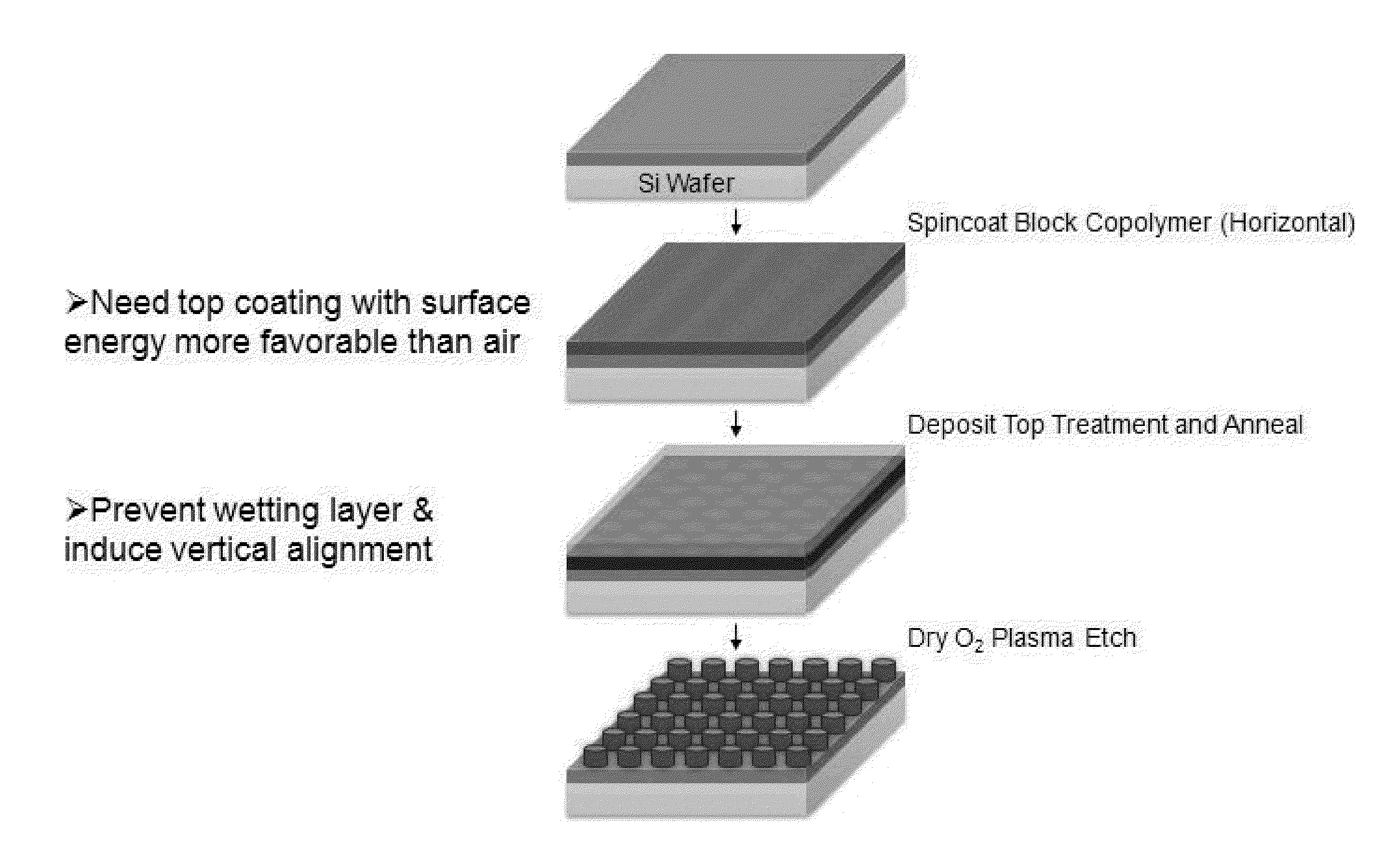
[0083]One example of the method of using chemical vapor deposited films to control domain orientation in block copolymer thin films: 1) Surface energy neutralizing layer polymer is dissolved in toluene and spin coated, 2) Cross-linked at 250° C. for 5 minutes, 3) Washed with toluene 2 times, 4) Block copolymer is dissolved in toluene and spin coated, 5) Post apply bake at 110° C. for 1 minute, 6) The parylene containing treatment composition is vacuum deposited onto block copolymer with a thickness of approximately 150 nm forming a top coat, 7) Anneal the thin films at 170° C. for 18 hours, 8) Oxygen plasma etch the block copolymer with the following conditions: Pressure=90 mTorr, RF Power=80 W, ICP Power=100 W, O2 flow rate=5 standard cubic centimeters per minute (SCCM), temperature=15° C., time=35 seconds.

[0084]See FIG. 15 and FIG. 16.

example 2

An Alternate Procedure Using Two Chemical Vapor Deposited Layers to Control Domain Orientation in Block Copolymer Thin Films

[0085]One example of the method of using chemical vapor deposited films to control domain orientation in block copolymer thin films: 1) The parylene containing surface energy neutralizing layer is vacuum deposited onto the wafer, 2) Block copolymer is dissolved in toluene and spin coated, 3) Post apply bake at 110° C. for 1 minute, 4) The parylene containing treatment composition is vacuum deposited onto block copolymer with a thickness of approximately 150 nm forming a top coat, 5) Anneal the thin films at 170° C. for 18 hours, 6) Oxygen plasma etch the block copolymer with the following conditions: Pressure=90 mTorr, RF Power=80 W, ICP Power=100 W, O2 flow rate=5 standard cubic centimeters per minute (SCCM), temperature=15° C., time=35 seconds.

[0086]See FIG. 18 and FIG. 19.


PUM

PropertyMeasurementUnit
Temperatureaaaaaaaaaa
Structureaaaaaaaaaa
Surface energyaaaaaaaaaa

Abstract

The present invention uses vacuum deposited thin films of material to create an interface that non-preferentially interacts with different domains of an underlying block copolymer film. The non-preferential interface prevents formation of a wetting layer and influences the orientation of domains in the block copolymer. The purpose of the deposited polymer is to produce nanostructured features in a block copolymer film that can serve as lithographic patterns.

Description

[0001]This application claims the benefit of priority to Provisional Application U.S. Ser. No. 61 / 597,295, which was filed on Feb. 10, 2012, the disclosures of which are incorporated herein by reference.FIELD OF THE INVENTION[0002]The present invention uses vacuum deposited thin films of material to create an interface that non-preferentially interacts with different domains of an underlying block copolymer film. The non-preferential interface prevents formation of a wetting layer and influences the orientation of domains in the block copolymer. The purpose of the deposited polymer is to produce nanostructured features in a block copolymer film that can serve as lithographic patterns.BACKGROUND OF THE INVENTION[0003]The improvement in areal density in hard disk drives using conventional multigrain media is currently bound by the superparamagnetic limit [1]. Bit patterned media can circumvent this limitation by creating isolated magnetic islands separated by a nonmagnetic material. N...

Claims


Application Information

Patent Timeline
IPC IPC(8): C23C16/44B29C43/32
CPCB29C43/32C23C16/44B81C1/00031Y10T428/24802B81C2201/0149B82Y10/00B82Y40/00G03F7/0002Y10S977/788Y10S977/809Y10S977/811Y10S977/839Y10S977/888Y10S977/89Y10S977/891Y10T428/31504Y10T428/31663Y10T428/31931C03C17/30C03C17/3405C03C17/42C03C2218/152C09D153/00
Inventor WILLSON, CARLTON GRANTDURAND, WILLIAM J.ELLISON, CHRISTOPHER JOHNBATES, CHRISTOPHER M.SESHIMO, TAKEHIROCUSHEN, JULIASANTOS, LOGAN J.DEAN, LEONRAUSCH, ERICA L.
Owner BOARD OF RGT THE UNIV OF TEXAS SYST
Why Eureka
Try Eureka