Vehicle control and gateway module

a gateway module and vehicle control technology, applied in vehicle position/course/altitude control, process and machine control, instruments, etc., can solve problems such as difficult to determine precisely which portion, restricting material flow, and difficult to balance the system for even seed and particulate dispersion

Active Publication Date: 2013-08-15
INTELLIGENT AGRI SOLUTIONS
View PDF18 Cites 71 Cited by
  • Summary
  • Abstract
  • Description
  • Claims
  • Application Information

AI Technical Summary

Benefits of technology

[0024]In accordance with the teachings of the present invention, a particulate flow measurement, monitoring and balancing system is disclosed. The system has a particular use for monitoring and measuring the particulate flow in a pneumatic system such as an air seeder, such particulate flow consisting of seeds, fertilizer, or a combination of both seeds and fertilizer; and, based upon data derived from sensors in the system, provide a means to simply and effectively balance the material flow being dispensed by a plurality of seed tubes so as to affect uniform distribution of the material across the field. Each system consists of a plurality of discrete sensors placed in the particulate flow tubes such that the signals received are analyzed by a computational means, the data from which is transmitted to a central operator interface.
[0025]Each discrete sensor consists of an acoustic sensing means which is placed into the flow of material such that substantially all of the particulate traveling in the tube strikes the sensing means. In striking the sensing means, the particulate undergoes a change in momentum resulting in an impulse of energy being transferred from the material into sound power. The sound power is directed by an acoustic pathway onto a MEMS microphone, the output of which is digitized and analyzed with respect to energy and frequency. Numerous acoustic pathways are directed to a single computational means, thus reducing the complexity of the system and the number of required electrical connections.
[0027]A new vehicle control and gateway module will be described. The invention described herein is centered around an electronics module called the gateway module, which acts as a bridge between the proprietary communication busses standard on a vehicle (such as those commonly seen on commercial agricultural and construction vehicles, including the standardized communication busses used for operator displays in the vehicle), and various external, remotely-located wireless networks (including but not limited to personal area networks, local area networks (LANs), mesh networks, wide area networks (WANs), metropolitan area networks, and cellular networks). The gateway module receives messages from one system (from one or more of the vehicle busses or from one or more of the off-board wireless networks), interprets the message, translates it into a form appropriate to the receiving system, and transmits it to the receiving system seamlessly. This allows a mobile device to access data from the vehicle as needed, or even to be used as a controller for the vehicle. It also allows an application programming interface (API) to be created that will allow an external, web-based application to access and use vehicle-generated data (such as vehicle service information, vehicle or implement status, seed or chemical quantity, etc.).

Problems solved by technology

However, once the material leaves the hopper, it is difficult to determine precisely which portion takes which specific path through the branching network of tubes to eventually make its way to the end of the seed tubes and be placed into the soil.
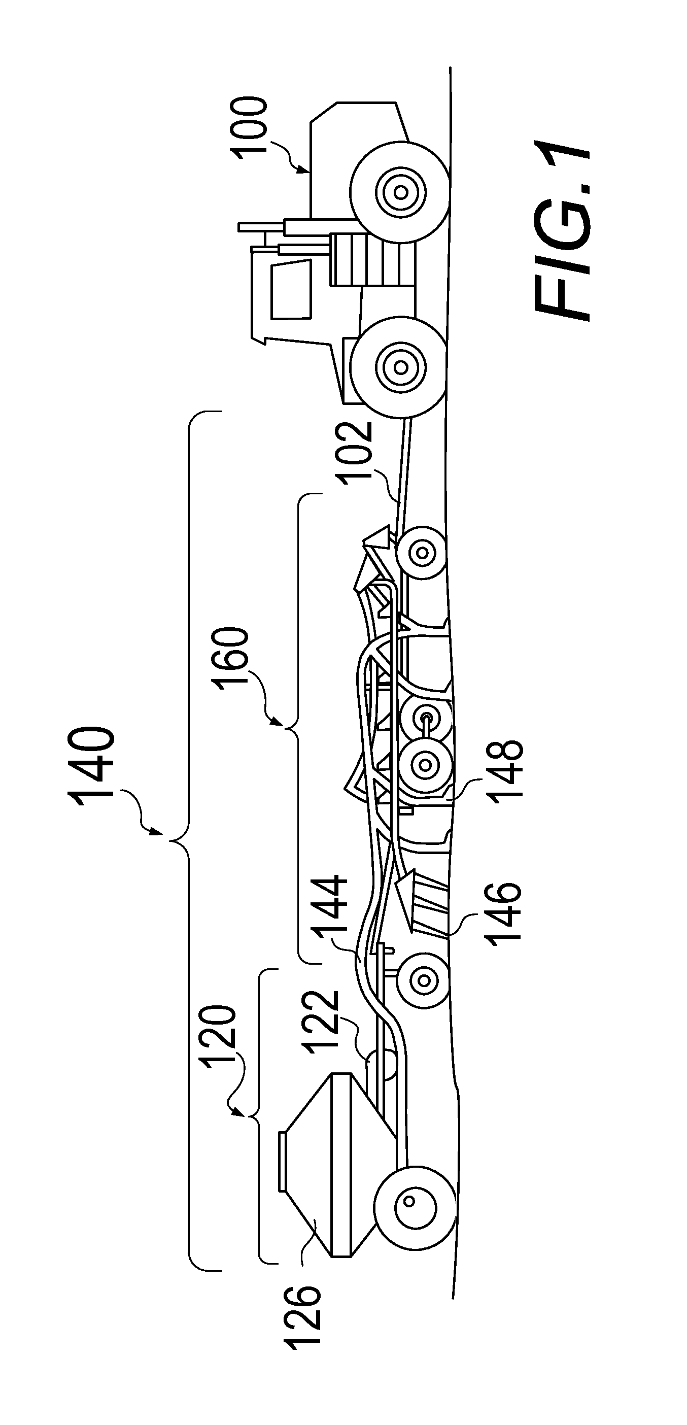
An air seeding system represents a complex fluid dynamics problem, in which a single initial flow of air and suspended 
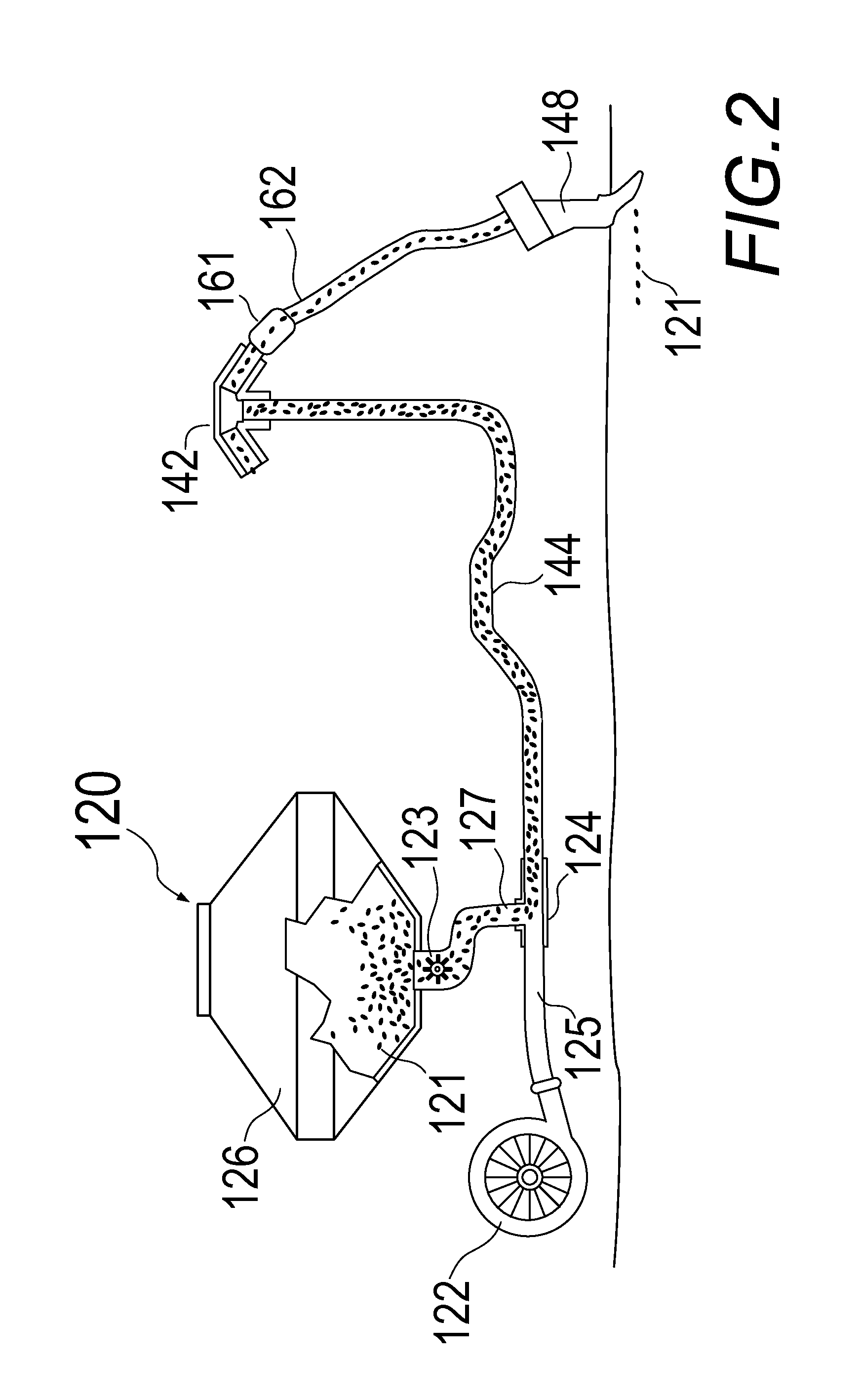
particulate material may be continuously divided and redirected through multiple tubes to manifold towers where it is then split off into branching seed tubes of varying lengths to a point of eventual discharge into the soil.
Sharp turns, bends, and forks in the distribution tubes cause restrictions on the material flow, and make balancing the system for even seed and particulate dispersal problematic.
If a partial or full blockage develops in one or more of the particulate flow tubes, air flow (and, therefore, particulate flow) increases proportionately in the remaining tubes, further complicating the balancing problem.
A partial blockage will still allow some amount of air and material to flow past it, but will reduce the flow noticeably.
A full blockage will not allow any material to flow past it (although it may be possible for a small amount of air to leak past a full blockage).
These optical sensors are subject to a number of problems particular to the technology.
One such problem is caused by the non-uniformity of the intensity of the light beam used to sense the particles moving in the tube.
Hence, the amount of material passing in the tube is not directly correlated to the amount of light that reaches the optical sensor, which can result in an incorrect determination of the actual amount of material passing in the tube.
In addition, the optical sensors may not be able to detect at all certain material that is moving through locations in the seed tubes that are not covered by the beam.
Attempts to create more uniform or more complete light beams to correct these problems have been inadequate or overly complex.
As a result, although in optimal conditions optical sensing systems may work well in detecting total tube blockage, they are not very effective in measuring overall material flow, particularly in situations where a great deal of material is flowing in the tubes.
Optical-based seed monitoring systems are also susceptible to problems in normal use caused by a build-up of dust and other foreign matter that can be found inside an air seeder.
Often this build up is gradual, causing the sensor to lose calibration over time, becoming less capable of accurately detecting material flow.
This build-up can ultimately block sensors and / or light sources completely, causing the system to determine that a large amount of material is moving through the seed tube, or that a blockage has occurred.
Another source of inaccurate readings in an optical seed monitoring system is that when two or more particles happen to line up in such a manner that an imaginary line drawn between them is parallel to the axis of the beam of light from the transmitter to the receiver, one particle can occlude another, causing them to be read as a single particle instead of multiple particles.
In other words, one or more particles can hide in the shadow of another particle as they pass through the beam and not have an effect on the quantity of the light reaching the sensor, adversely affecting the ability of the sensor to accurately measure material flow.
Further compounding this problem is that not all particles are uniformly shaped (i.e. spherical).
As a result, it is generally not possible to tell with a reasonable degree of accuracy the amount of material moving past an optical sensor in an air seeder.
However, piezoelectric sensors have a number of characteristics that can limit their usefulness when used in an air seeding application or other similar harsh environments.
The sensors are high impedance and hence susceptible to interference by strong voltage fields in the environment.
This is particularly a problem in an environment like that of an air seeder, where collisions of seeds, dust, fertilizer and other particles generate a large amount of static electricity, and where high electromagnetic field strengths are likely.
Placing the sensing electronics in these areas, as dictated by the necessity to place the high impedance piezoelectric sensors close to their electronic discrimination circuitry, exposes them to premature failure as a result of electrostatic discharge and circuit overvoltage.
Another problem with piezoelectric sensors is that the crystal is prone to damage by cracking if overstressed.
Being so placed, the piezoelectric sensors are subject to damage through impact and abrasion in being stuck by numerous, large, or fast moving particles in the air stream (small stones, for example) over a prolonged period of time.
Further complicating matters, even though these sensors are placed directly in the path of material flow, they are characteristically struck by a relatively small portion of the total material flowing in the sensor tube, and hence are incapable of accurately measuring the total amount of material flowing in the line due to the relatively small amount of material that actually strikes the sensor.
However, a major drawback of this implementation is that material often gets lodged in the sensor tube because of the pin obstructing a portion of the flow path.
Another serious drawback of this design is that the pins often fail after a period of use due to being repeatedly struck by the particles in the air stream.
These sensors also fail to accurately measure the amount of material flowing in the line because only very small amount of the material actually strikes the pin.
Yet another drawback to currently deployed piezoelectric sensor based systems, or any prior art system that places electronic sensors in or near to the stream of material, is that they require that the electronics associated with the sensors be replicated in every location where the sensors are installed.
With current state-of-the-art air seeders employing a hundred or more tubes, the cost of these sensors, if deployed in every tube, can become a significant impediment to the deployment of the system.
The assumption is that, if a material distribution line leaving the distribution manifold becomes blocked, the amount of material entering the manifold will decrease, causing the noise generated to decrease, which will indicate that a line is blocked.
However, this system suffers from a number of serious shortcomings, principal of which is the lack of sensitivity of the system to partial blockages, whereby the flow to an individual tube may become partially restricted without substantially changing the total material flow into the distribution manifold; inasmuch as airflow and hence material flow will increase in the remaining distribution lines should one or more distribution lines become partially blocked.
Additionally, since this system is designed as a blockage monitoring system, it lacks both the sensitivity and granularity to be used as a material flow measurement system.
Finally, this system, and others like it that do not use a sensor in each final run, are incapable of being used to help balance the flow of material across the final distribution runs of an air seeder system.
This is obviously a laborious process which may have to be repeated multiple times as an individual is attempting to balance a system.
Even if sensors described in prior art are used in every secondary seed tube on an air seeder, these sensors are not, for the most part, designed to measure material flow, but rather are designed to detect lack of material flow (blockage).
Assuming these sensors could be used to accurately measure material flow, there still is currently no efficient way of balancing the outputs of these tubes based on the data from the sensors.
Some air seeding systems utilize hinged diverters or baffles at a branching point in a tube to direct more or less air flow down one of the two branches, but this can only affect the flow of the two branches of that particular tube in relation to each other, and does not correct any imbalance which may exist further downstream in the system.
Another problem common to all modern air seeders is the severe environmental conditions under which the equipment must operate.
It is undesirable to introduce components into this environment that by virtue of their electrical complexity are prone to failure.
Unfortunately, that is precisely the situation with many of the flow monitoring systems in use today.
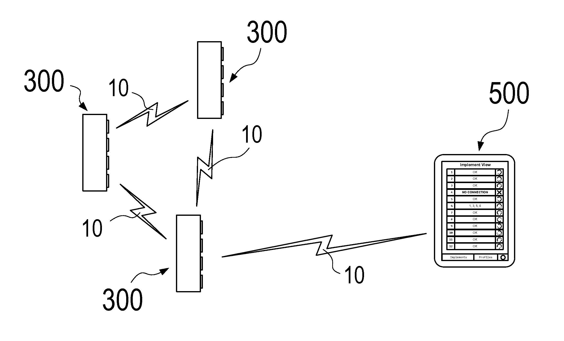
Monitor systems of the present art, for the most part, employ sensors which are uniquely powered and addressed, resulting in hundreds of connections which are prone to failure due to the severe environmental conditions under which they must operate.
Designing and manufacturing monitors and other interface devices for retrofitting on existing equipment can be challenging due to the wide variety of equipment systems and functions which must be accommodated.
“Virtual terminals” meeting industry-standard protocol requirements and compatible with various vehicles and implements are commercially available, but are often subject to cost, performance and installation disadvantages.

Method used


Image

  • Vehicle control and gateway module
  • Vehicle control and gateway module
  • Vehicle control and gateway module

Examples


embodiment or aspect

Alternative Embodiment or Aspect

[0170]Referring now to FIGS. 15 through 24B, FIG. 15 is a software architecture diagram showing the various layers of software resident in at least one embodiment of a vehicle gateway module. In this view, the physical gateway module 1600 is shown as a dashed line to indicate that the software layers depicted represent various pieces of software embedded within the gateway module 1600. Additional detail on the gateway module 1600 (the hardware) will be presented in FIG. 16.

[0171]The software architecture of at least one embodiment of a gateway module 1600 includes a hardware interface layer 1500, which includes routines for interfacing to and controlling the various physical hardware devices and components that will be further explained in connection with FIG. 16. The hardware interface layer 1500 is essentially the firmware that controls the primary functions of the physical hardware components.

[0172]The architecture also contains an ISO 11783 softwa...

case examples

IV. Use Case Examples

[0206]Use Case 1: Implement / attachment with ECUs that have never been “paired” to a Gateway.[0207]Step 1: The operator initiates the pairing mode on the Gateway (Access Point) from the display terminal.[0208]Step 2: The Gateway changes its normal SSID (for example: GW_FF21, where FF21 is the serial number) to the specially coded SSID GW_FF21_XXXX_YYYYYY_############ where ############ is the security key of the network, XXXX is the implement / attachment manufacturer ID and YYYYYY is the implement / attachment serial number.[0209]Step 3: The Wi-Fi ECUs on the implement / attachment are actively looking for a Gateway to pair with (since they are un-paired) find the specially code SSID being broadcast and request to join the Gateway using the SSID and security key.[0210]Step 4: Once the Wi-Fi ECUs have joined the Gateway and gained network level access they send the Gateway messages requesting application level access.[0211]Step 5: The operator is notified that Wi-Fi EC...


PUM


Abstract

A vehicle control and gateway module comprising an electronic control module controlling one or more vehicle systems, a vehicle communications bus, a wireless communications module, an electronic gateway module acting as a translator of information between the vehicle communications bus and the wireless communications module, and a software program, whereby an operator using a remote mobile device can send and receive wireless commands to and from the vehicle with the electronic gateway module translating messages from one data protocol to the other as required.

Description

CROSS-REFERENCE TO RELATED APPLICATION[0001]This patent application is a continuation-in-part of and claims priority in U.S. patent application Ser. No. 13 / 046,549, entitled Air Seeder Monitoring and Equalization System Using Acoustic Sensors, filed on Mar. 11, 2011. The entire disclosure of the above-noted patent application is incorporated by reference in its entirety herein.BACKGROUND OF THE INVENTION[0002]1. Field of the Invention[0003]The present invention relates generally to a material flow monitoring and equalization system, and more particularly to a system for measuring and balancing the flow of seeds and / or other material through an air seeding system using acoustic sensors and adjustable flow restrictors. This invention also relates generally to certain new and useful improvements in vehicle control, and, more particularly, to a control system allowing wireless access to and control of a vehicle's subsystems.[0004]2. Description of the Related Art[0005]The general princi...

Claims


Application Information

Patent Timeline
Patent Type & Authority Applications(United States)
IPC IPC(8): G06F17/00
CPCG06F17/00G01F1/666A01C7/105A01C7/081G08C2201/93
Inventor THUROW, BRADLEY R.WIIG, JOHAN A.GELINSKE, JOSHUA N.REICH, ADAM A.BATCHELLER, BARRY D.
Owner INTELLIGENT AGRI SOLUTIONS
Why Eureka
Try Eureka