Integrated hydrotreating, solvent deasphalting and steam pyrolysis process for direct processing of a crude oil

a technology of integrated hydrotreating and steam pyrolysis, which is applied in the direction of hydrocarbon oil treatment products, thermal non-catalytic cracking, solvent deasphalting, etc. it can solve the problems of coke formation, high cost and energy consumption, and limited availability of feedstocks for conventional heavy hydrocarbon pyrolysis operations, etc. , to achieve the effect of reducing the correlation index of the bureau of mines, reducing the content and increasing paraffinity

Active Publication Date: 2013-08-29
SAUDI ARABIAN OIL CO
View PDF3 Cites 49 Cited by
  • Summary
  • Abstract
  • Description
  • Claims
  • Application Information

AI Technical Summary

Benefits of technology

[0016]The integrated hydrotreating, solvent deasphalting and steam pyrolysis process comprises charging the crude oil to a hydroprocessing zone operating under conditions effective to produce a hydroprocessed effluent having a reduced content of contaminants, an increased paraffinicity, reduced Bureau of Mines Correlation Index, and an increased American Petroleum Institute gravity; charging the hydroprocessed effluent to a solvent deasphalting zone with an effective amount of solvent to produce a deasphalted and demetalized oil stream and a bottom asphalt phase; thermally cracking the deasphalted and demetalized oil stream in the presence of steam to pro...

Problems solved by technology

The availability of these feedstocks is usually limited and requires costly and energy-intensive process steps in a crude oil refinery.
A major drawback in conventional heavy hydrocarbon pyrolysis operations is coke formation.
In a comparative example without the addition o...

Method used


Image

  • Integrated hydrotreating, solvent deasphalting and steam pyrolysis process for direct processing of a crude oil
  • Integrated hydrotreating, solvent deasphalting and steam pyrolysis process for direct processing of a crude oil
  • Integrated hydrotreating, solvent deasphalting and steam pyrolysis process for direct processing of a crude oil

Examples


Embodiment Construction

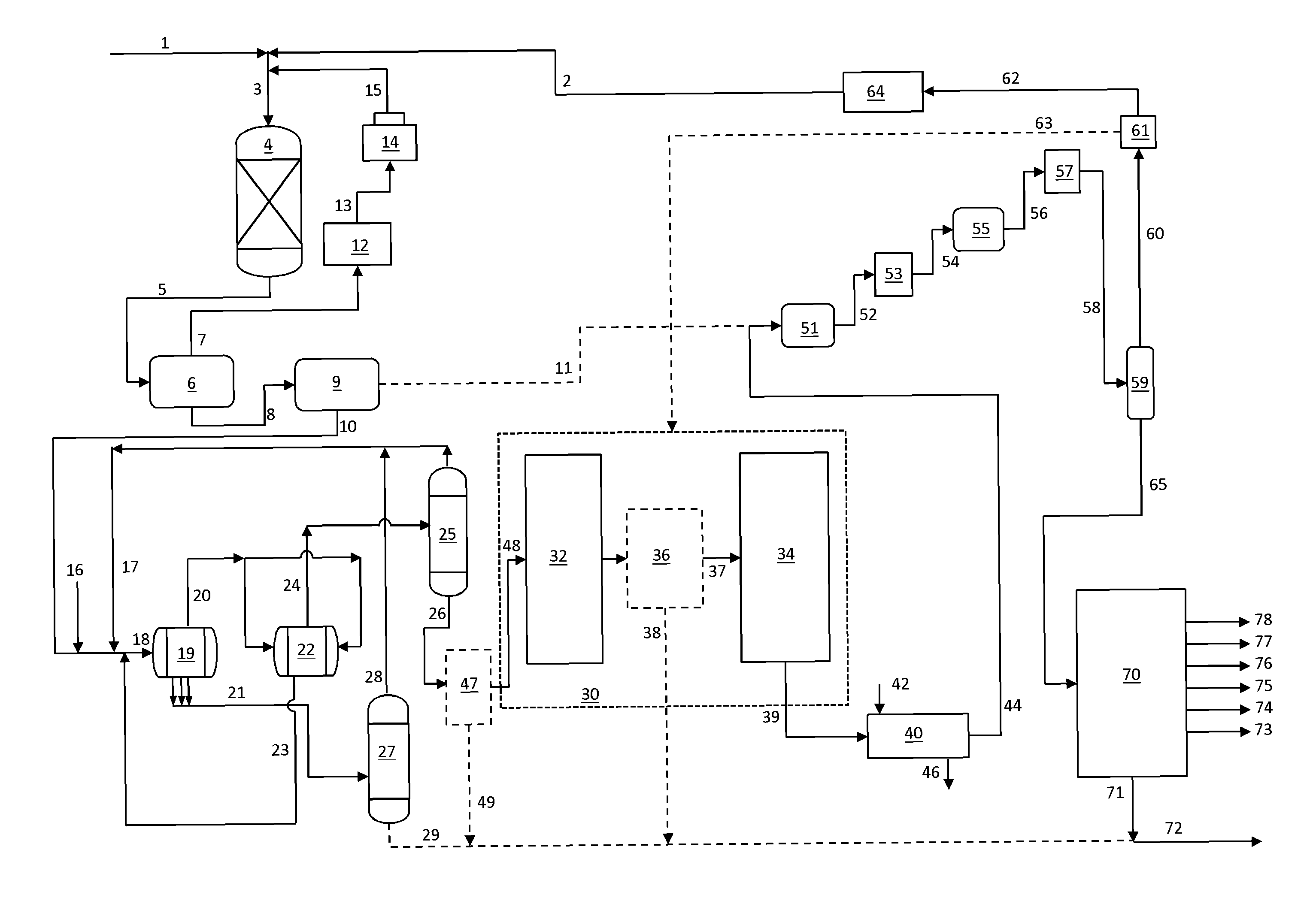
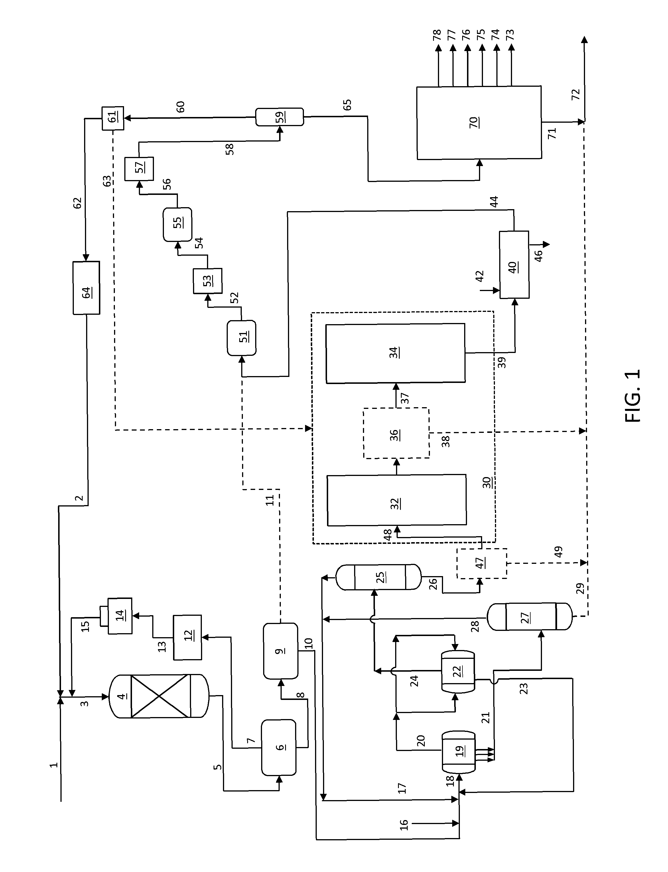
[0023]A flow diagram including an integrated hydrotreating, solvent deasphalting and steam pyrolysis process and system is shown in FIG. 1. The system includes a selective hydroprocessing zone, a solvent deasphalting zone, a steam pyrolysis zone and a product separation zone.

[0024]The selective hydroprocessing zone includes a reactor zone 4 including an inlet for receiving a combined stream 3 including a crude oil feed stream 1 and hydrogen 2 recycled from the steam pyrolysis product stream, and make-up hydrogen if necessary (not shown). Reactor zone 4 also includes an outlet for discharging a hydroprocessed effluent 5.

[0025]Reactor effluents 5 from the hydroprocessing reactor(s) are cooled in a heat exchanger (not shown) and sent to a high pressure separator 6. The separator tops 7 are cleaned in an amine unit 12 and a resulting hydrogen rich gas stream 13 is passed to a recycling compressor 14 to be used as a recycle gas 15 in the hydroprocessing reactor. A bottoms stream 8 from t...


PUM


Abstract

A process is provided that is directed to a steam pyrolysis zone integrated with a hydrotreating zone and a solvent deasphalting zone to permit direct processing of crude oil feedstocks to produce petrochemicals including olefins and aromatics. The integrated hydrotreating, solvent deasphalting and steam pyrolysis process comprises charging the crude oil to a hydroprocessing zone operating under conditions effective to produce a hydroprocessed effluent reduced having a reduced content of contaminants, an increased paraffinicity, reduced Bureau of Mines Correlation Index, and an increased American Petroleum Institute gravity; charging the hydroprocessed effluent to a solvent deasphalting zone with an effective amount of solvent to produce a deasphalted and demetalized oil stream and a bottom asphalt phase; thermally cracking the deasphalted and demetalized oil stream in the presence of steam to produce a mixed product stream; separating the mixed product stream; purifying hydrogen recovered from the mixed product stream and recycling it to the hydroprocessing zone; recovering olefins and aromatics from the separated mixed product stream; and recovering pyrolysis fuel oil from the separated mixed product stream.

Description

RELATED APPLICATIONS[0001]This application claims the benefit of priority under 35 USC §119(e) to U.S. Provisional Patent Application No. 61 / 789,643 filed Mar. 15, 2013, and is a Continuation-in-Part under 35 USC §365(c) of PCT Patent Application No. PCT / US13 / 23335 filed Jan. 27, 2013, which claims the benefit of priority under 35 USC §119(e) to U.S. Provisional Patent Application No. 61 / 591,776 filed Jan. 27, 2012, all of which are incorporated herein by reference in their entireties.BACKGROUND OF THE INVENTION[0002]1. Field of the Invention[0003]The present invention relates to an integrated hydrotreating, solvent deasphalting and steam pyrolysis process for direct processing of a crude oil to produce petrochemicals such as olefins and aromatics.[0004]2. Description of Related Art[0005]The lower olefins (i.e., ethylene, propylene, butylene and butadiene) and aromatics (i.e., benzene, toluene and xylene) are basic intermediates which are widely used in the petrochemical and chemica...

Claims


Application Information

Patent Timeline
IPC IPC(8): C10G69/06
CPCC10G45/00C10G55/04C10G67/0463C10G9/36C10G21/003C10G69/06C10G2300/308C10G2300/4081C10G2400/20C10G2400/30C10G2300/201C10G2400/22
Inventor BOURANE, ABDENNOURSHAFI, RAHEELSAYED, ESSAMABBA, IBRAHIM A.AKHRAS, ABDUL RAHMAN ZAFER
Owner SAUDI ARABIAN OIL CO
Why Eureka
Try Eureka