
Carbon pyrolyzate adsorbent having utility for co2 capture and methods of making and using the same

Inactive Publication Date: 2013-11-14
ENTEGRIS INC
View PDF0 Cites 30 Cited by
  • Summary
  • Abstract
  • Description
  • Claims
  • Application Information

AI Technical Summary

Benefits of technology

The patent text describes a new carbon material that can be used to capture carbon dioxide (CO2) from waste gases. The carbon material has specific physical and chemical properties that allow it to absorb CO2 at a high capacity and with high efficiency. The method involves pyrolyzing a resin material under special conditions to produce the carbon material. The resulting material can be used in a CO2 capture apparatus to absorb CO2 from gas emissions. The technical effects of this carbon material are improved efficiency and capacity for CO2 capture, which can help reduce emissions of CO2 and promote a cleaner environment.

Problems solved by technology

Current approaches being investigated for control of CO2 emissions from electric power plants include (i) cryogenic technology, (ii) amine-based absorbents, (iii) dilute alkali approaches, and (iv) chilled dilute ammonia absorbents, but these methods are sufficiently energy-intensive and expensive that their commercial viability is far from certain.
Porous metal-organic framework (MOF) materials are also being investigated, as well as zeolite materials, but zeolite materials are generally poorly suited to CO2 capture due to their selectivity for H2O over CO2.
MOF materials exhibiting high CO2 capacities only at high operating pressures or at low temperatures are not viable since the additional costs of processing that are associated with such operating conditions may gauge the value of any capacity advantages possessed by such materials.
Similarly, MOF materials that exhibit high heats of adsorption for CO2 require uneconomical and difficult regeneration conditions (e.g., excessively high temperatures or low pressures).
MOF materials exhibiting poor hydrothermal stability or high H2O uptake are also not viable candidates.
Thus, there is a lack of proven, acceptable CO2 capture materials and processes.

Method used


Image

  • Carbon pyrolyzate adsorbent having utility for co2 capture and methods of making and using the same
  • Carbon pyrolyzate adsorbent having utility for co2 capture and methods of making and using the same
  • Carbon pyrolyzate adsorbent having utility for co2 capture and methods of making and using the same

Examples


example 1

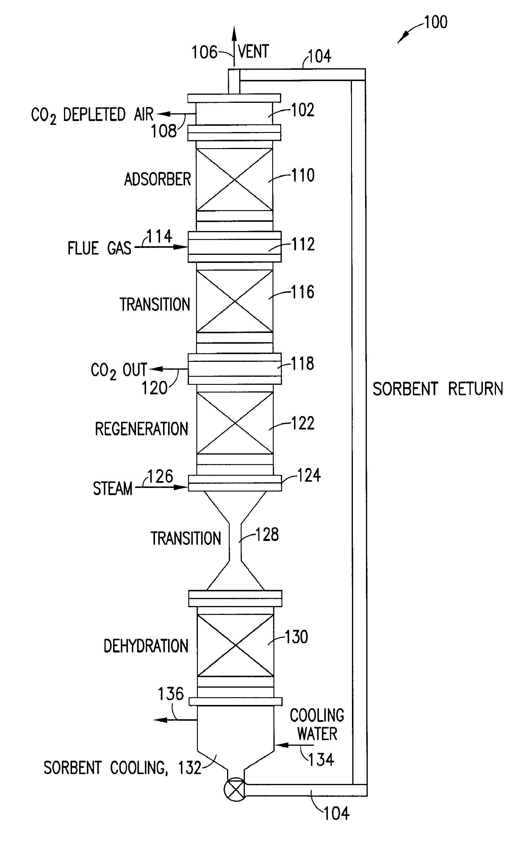
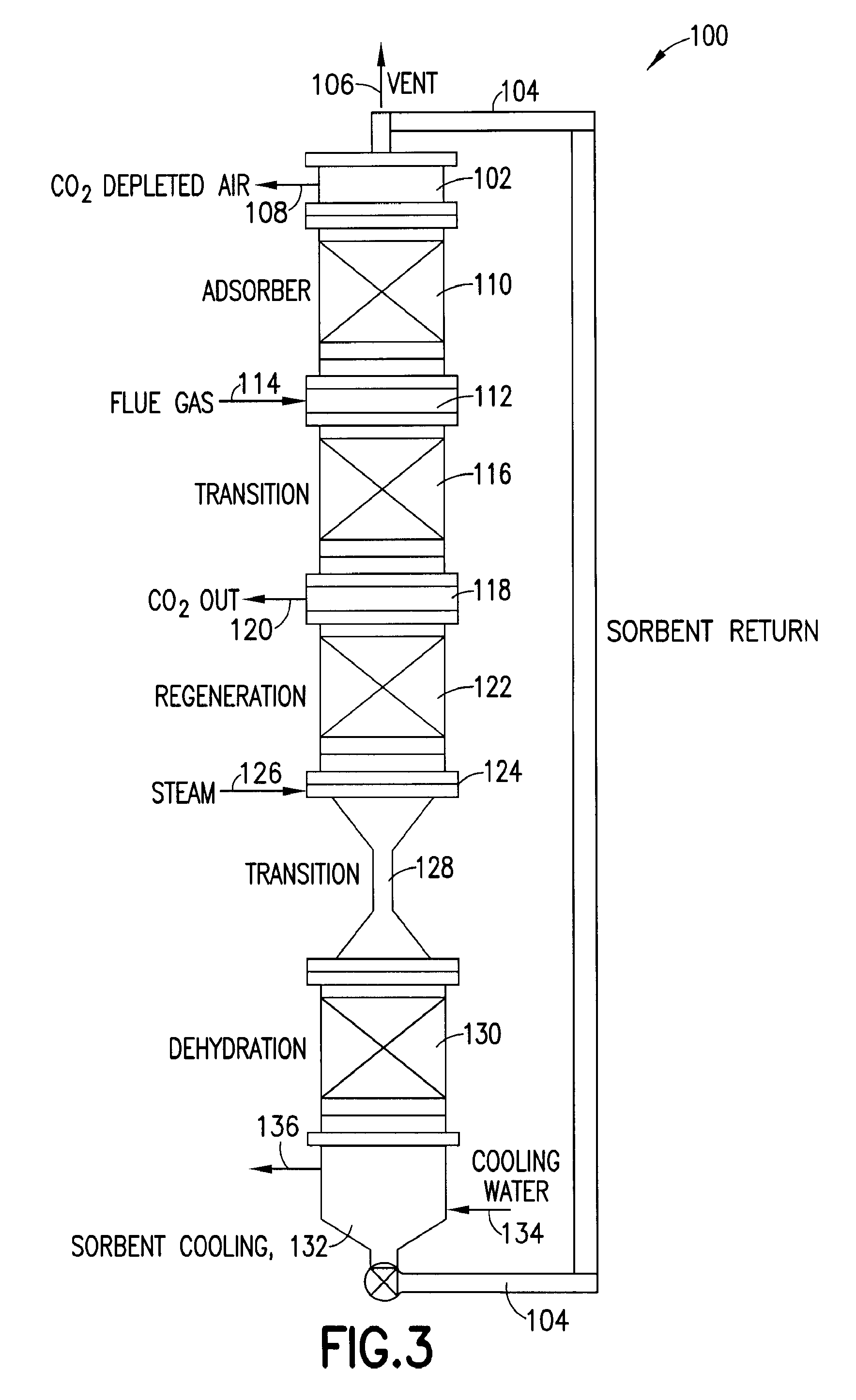
[0080]A CO2 capture process was carried out, using a circulating, falling stream of granules of carbon pyrolyzate adsorbent to separate an incoming stream of flue gas. The carbon pyrolyzate adsorbent utilized in this example had the following characteristics: a CO2 adsorption capacity measured at 1 atm pressure of CO2 of 20 percent by weight, based on weight of the adsorbent; an activation energy of 2 by the adsorbent; heat of adsorption and heat of desorption each being in a range of 25 to 28 kJ / mole; high hydrothermal stability; mechanical stability over at least 50,000 adsorption / desorption cycles; spherical granule form of the carbon pyrolyzate adsorbent, with granule diameter being in a range of from 100 to 300 μm; agglomeration resistance at temperature of 100° C.; heat capacity of 1 J / g / K; thermal conductivity of 0.8 w / m-K; and hydrophobicity of the carbon pyrolyzate material.

[0081]The flue gas in the CO2 capture process was separated into a CO2-lean flue gas stream in which ...


PUM

PropertyMeasurementUnit
Fractionaaaaaaaaaa
Pore sizeaaaaaaaaaa
Pore sizeaaaaaaaaaa

Abstract

A particulate form carbon pyrolyzate adsorbent, having the following characteristics: (a) CO2 capacity greater than 105 cc / gram at one bar pressure and temperature of 273° Kelvin; (b) CO2 Working Capacity greater than 7.0 weight percent; (c) CO2 heats of adsorption and desorption each of which is in a range of from 10 to 50 kJ / mole; and (d) a CO2 / N2 Henry's Law Separation Factor greater than 5. The carbon pyrolyzate material can be formed from a polyvinylidene chloride-based polymer or copolymer, or other suitable resin material, to provide an adsorbent that is useful for carbon dioxide capture applications, e.g., in treatment of flue gases from coal-fired power generation plants.

Description

CROSS-REFERENCE TO RELATED APPLICATION[0001]The benefit of priority under 35 USC 119 of U.S. Provisional Patent Application 61 / 438,081 filed Jan. 31, 2011 in the names of Melissa A. Petruska, J. Donald Carruthers, Edward A. Sturm, Shaun M. Wilson, and Joshua B. Sweeney for “CARBON PYROLYZATE ADSORBENT HAVING UTILITY FOR CO2 CAPTURE AND METHODS OF MAKING AND USING THE SAME” is hereby claimed. The disclosure of U.S. Provisional Patent Application 61 / 438,081 is hereby incorporated herein by reference, in its entirety, for all purposes.FIELD[0002]The present disclosure relates to a carbon pyrolyzate adsorbent that is useful for carbon dioxide capture, e.g., from CO2-containing gas streams discharged from coal-fired electric power plants, from oil refinery preheaters, from industrial boilers, and the like. The disclosure additionally relates to CO2 capture apparatus utilizing such carbon material and to methods of making and using the carbon pyrolyzate adsorbent.DESCRIPTION OF THE RELATE...

Claims


Application Information

Patent Timeline
IPC IPC(8): B01J20/20B01D53/047B01D53/04C01B32/50
CPCB01J20/20B01D53/04B01D53/047B01D53/0462B01D53/02B01D2253/102B01D2257/504B01D2258/0283B01J20/3078B01J20/28004B01J20/28011B01D53/0438Y02C20/40B01J20/02B01J19/26B01D53/08
Inventor PETRUSKA, MELISSA A.CARRUTHERS, J. DONALDSTURM, EDWARD A.WILSON, SHAUN M.SWEENEY, JOSHUA B.
Owner ENTEGRIS INC
Learn More