Battery electrode and a method for producing same

a battery electrode and electrode material technology, applied in the field of battery electrodes, can solve the problems of high cost, complex and expensive production of uncoated arrester regions using these methods, and the shape and arrangement of arrester regions on the electrode material are greatly restricted, so as to achieve high edge quality, reduce energy input, and maintain low thermal loading of the electrode material

Active Publication Date: 2013-11-14
ZENT FUR SONNENENERGIE & WASSERSTOFF FORSCHUNG BADEN WURTTEMBERG GEMEINNUTZIGE STIFTUNG
View PDF2 Cites 9 Cited by
  • Summary
  • Abstract
  • Description
  • Claims
  • Application Information

AI Technical Summary

Benefits of technology

[0021]Any suitable laser system, for example cutting or engraving laser systems, can be used for removing the material by means of laser ablation or for laser cutting. On account of the high edge quality and cutting precision in respect of cut guidance and penetration depth, high-quality arrester regions can be produced. Furthermore, by virtue of the use of ultra-short laser pulses, the energy input can be reduced, with the result that thermal loading of the electrode material is kept low. Since suitable laser systems are comparable to slot die systems in respect of cost, high purchase costs are not incurred.
[0022]A further aspect of the present invention specifies a battery which contains at least one battery electrode according to one of the above exemplary embodiments. Since the battery electrode can be designed to be relatively compact by forming an arrester region which is predominantly surrounded by a coating film, and therefore has a relatively low space requirement, a volumetric energy density of the battery can be increased.
[0023]A further aspect of the present invention specifies a method for producing a battery electrode, wherein a coating film is applied on a collector substrate. The coating film is then removed in an arrester region such that a circumference of the arrester region is predominantly surrounded, or at least half of the circumference of the arrester region is surrounded, by the coating film. Since the arrester region is formed by removing the coating film, the substantially completely coated collector substrate can be stored as electrode material without particular precautions and the arrester region can be formed only immediately before contact is made with the arrester region. In this way, impurities and chemical changes in the surface are avoided and a contact resistance in the arrester region is reduced. Furthermore, in this method, the coating film can be formed over a large surface area and / or virtually completely on an entire surface of the collector substrate. The coating film is possibly also formed on both sides of the collector substrate. Continuous coating technologies, for example doctor blade, comma bar and kiss coating, are advantageously used, with the result that the production costs can be reduced. Furthermore, the coated collector substrate has a uniform thickness, as a result of which a calendering process is simplified and improved.
[0024]In a preferred exemplary embodiment, the coating film in the arrester region is removed with a laser. In this case, a thin layer of the collector substrate can be removed in the arrester region at the same time in a preferred exemplary embodiment in order to improve a surface condition in the arrester region. The use of laser ablation for forming the arrester region increases the degree of freedom of design in the configuration of the battery electrode and the arrester region and allows for individual manufacture.

Problems solved by technology

However, forming relatively complex arrester regions using these methods is very complicated.
However, the following problems are encountered in the conventional methods for producing battery electrodes.
For example, the production of uncoated arrester regions by masking steps or brushing away the coating is very complex and expensive.
In the alternative production method by intermittent or continuous coating with the aid of a slot die system however, the possible shapes and arrangements of the arrester regions on the electrode material are greatly restricted.
In this case, the trend toward relatively small devices poses a particular challenge to battery production.
Firstly, batteries with relatively small dimensions therefore have to be developed, and secondly complex shapes are often required in order to make the most efficient use of the interior of a device as possible.
Furthermore, it is difficult to produce regular and clean edge regions between the coating region and the arrester region in the case of an intermittent coating method.
Furthermore, it is difficult and expensive to realize a variety of shapes of the electrodes with the conventional methods.
As a result however, the degree of freedom of design for the electrode shape is severely restricted because each electrode has to have an arrester region 40.
As a result, material consumption is increased and the production method is more expensive.
However, these stamping dies are very expensive on account of the high demands made on cutting quality.
However, this leads to unutilized space in the battery which is not filled with active electrode material.
As a result, the size of the battery is unnecessarily increased and / or an outer shape of the battery is fixed.
Furthermore, the arrester regions 40 can be easily contaminated in the conventional production methods or else during storage.
This has an adverse effect on the quality of an electrical contact between electrodes of the same kind and between the electrodes and an associated connection lug 50.
Since the arrester regions 40 are additionally formed before the calendering process during production of the electrode material, calendering is made more difficult on account of the non-uniformly thick structure.
In addition, the arrester region 40 which is formed by conventional methods may be poorly defined, wherein particularly an edge region of the arrester region 40 can be formed in an inaccurate and non-uniform manner.

Method used


Image

  • Battery electrode and a method for producing same
  • Battery electrode and a method for producing same
  • Battery electrode and a method for producing same

Examples


Embodiment Construction

[0035]The invention will be described below using the example of the lithium-ion battery which is distinguished by a high energy density and thermal stability. However, the present invention is not intended to be restricted to lithium-ion batteries but can be applied to any desired battery.

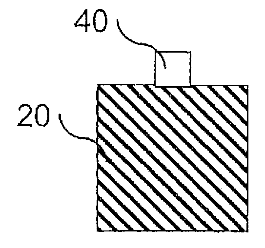
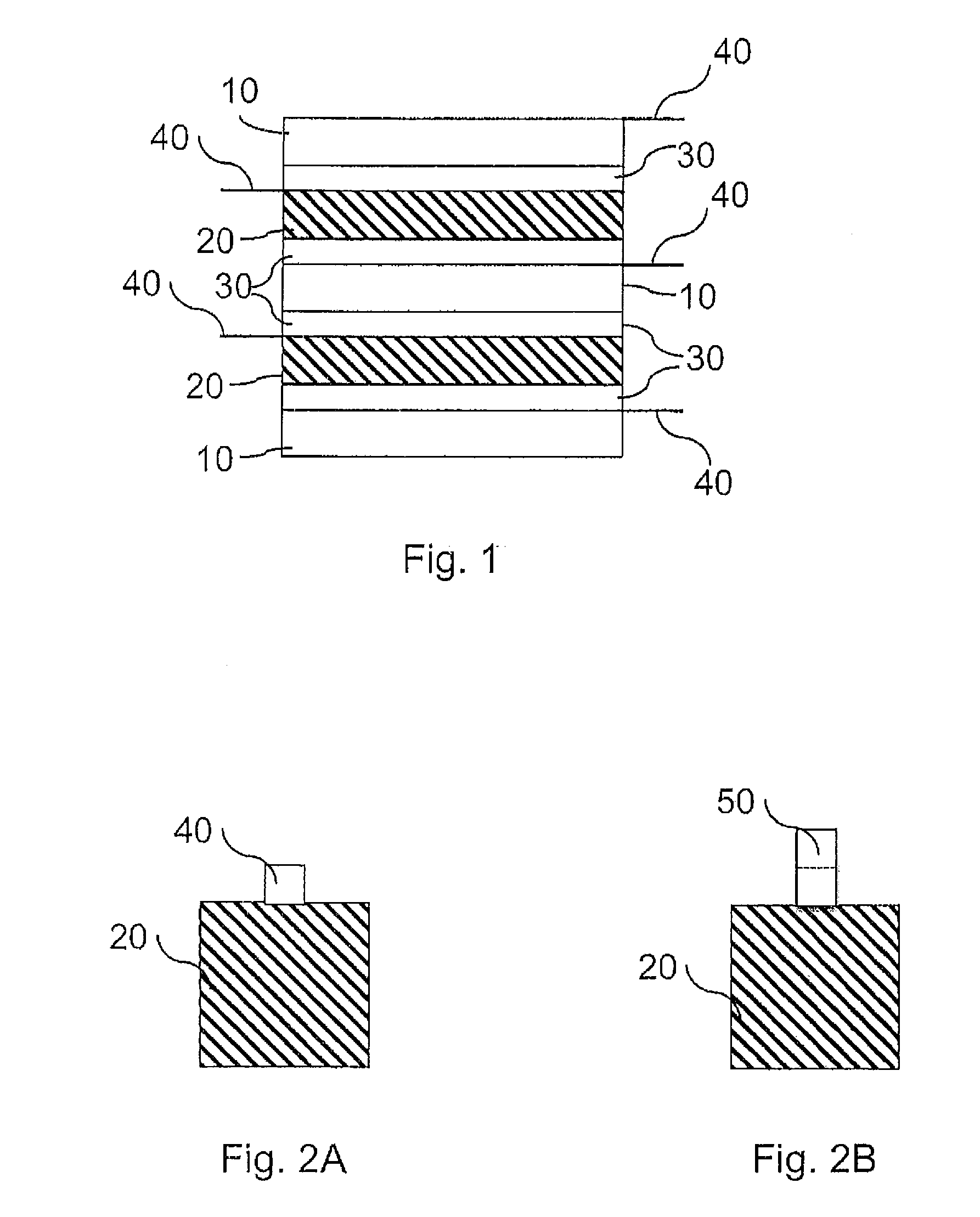
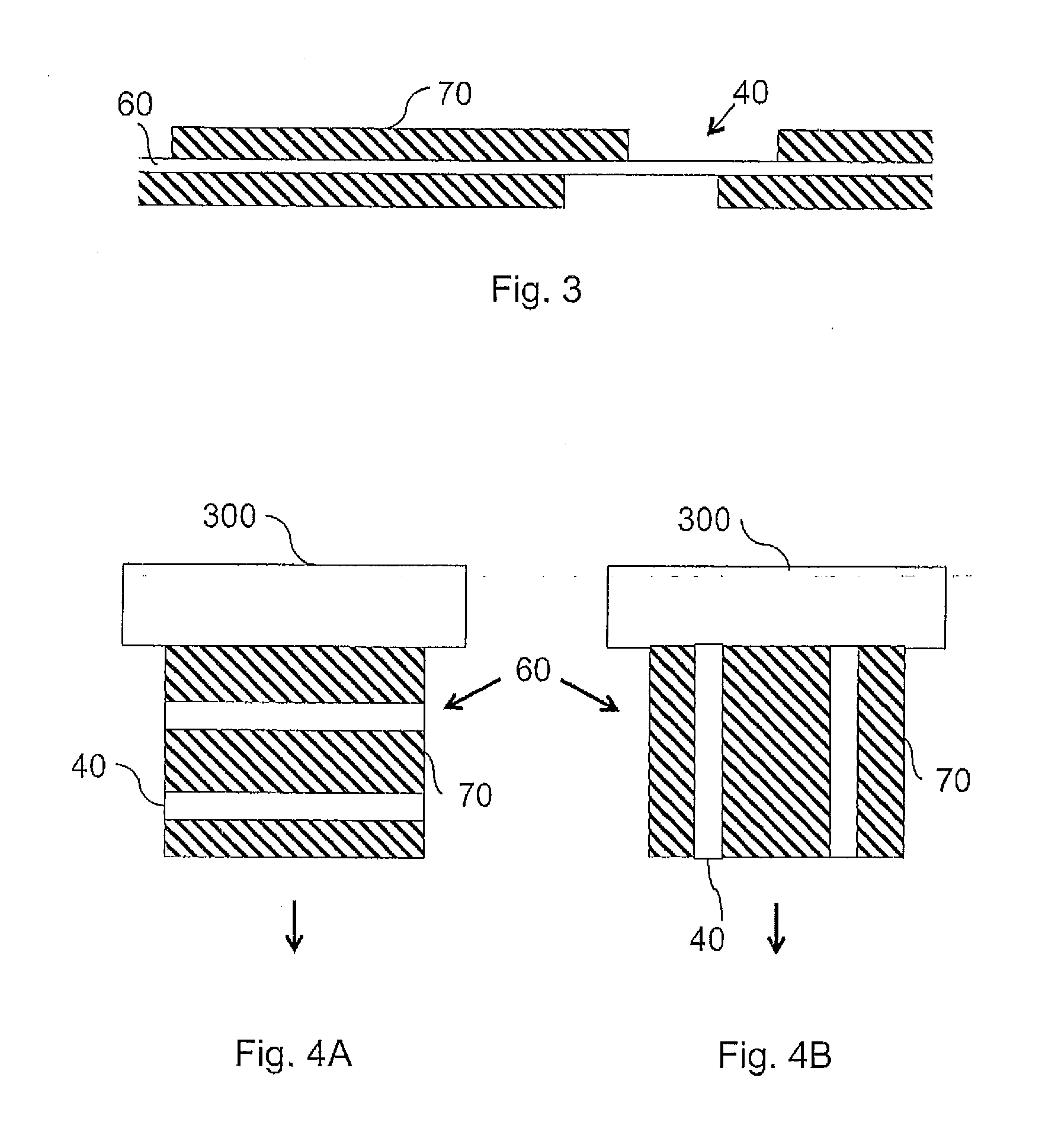
[0036]In a lithium-ion battery, a collector substrate 60 of an anode 10 is composed, for example, of copper which is coated with a coating film 70 which is composed of graphite, binder, carbon black and solvent. According to the present invention, the coating film 70 in an arrester region 40 is removed, with the result that the collector substrate 60 in the arrester region 40 is exposed. A connection lug 50, for example which is composed of nickel, can be mounted on the arrester region 40 of the anode 10. In the case of the cathode 20, a collector substrate 60 is composed, for example, of aluminum and is coated with a coating film 70 comprising an active material which contributes to a redox react...


PUM

PropertyMeasurementUnit
thicknessaaaaaaaaaa
wavelengthaaaaaaaaaa
thickaaaaaaaaaa

Abstract

In order to allow for a compact configuration of a battery with an increased energy density/volume ratio together with low production costs, the invention specifies a battery electrode and a method for producing same, wherein an arrester region is arranged on a collector substrate such that it is predominantly surrounded by a coating film.

Description

TECHNICAL FIELD[0001]The invention relates to a battery electrode and to a method for producing same.BACKGROUND TO THE INVENTION[0002]In general, a battery indicates both non-rechargeable primary cells and rechargeable secondary cells (also called rechargeable batteries). Batteries are classified on the basis of the underlying chemical redox reaction, the materials used, the electrical values (for example voltage or capacitance) or the geometric or structural design. Examples include alkaline-manganese batteries, zinc-carbon batteries or lithium batteries. A distinction is also drawn between winding cells and stacked batteries in batteries, depending on their inner construction. In the case of a winding cell, the electrode and separator layers which are arranged one above the other are wound up in a spiral manner and installed, for example, in a round battery with a cylindrical housing. In the case of a stacked battery however, a plurality of electrode and separator layers are alter...

Claims


Application Information

Patent Timeline
Patent Type & Authority Applications(United States)
IPC IPC(8): H01M4/70H01M4/04H01M50/531
CPCH01M4/70H01M4/0404H01M10/052H01M10/0585Y02E60/50Y02E60/10Y02P70/50H01M50/531H01M4/04H01M4/86H01M4/0402
Inventor STERN, RAINERKASPER, MICHAEL
Owner ZENT FUR SONNENENERGIE & WASSERSTOFF FORSCHUNG BADEN WURTTEMBERG GEMEINNUTZIGE STIFTUNG
Why Eureka
Try Eureka