

Activated fischer-tropsch synthesis reaction catalyst and method for producing hydrocarbons
- Summary
- Abstract
- Description
- Claims
- Application Information
AI Technical Summary
Benefits of technology
Problems solved by technology
Method used
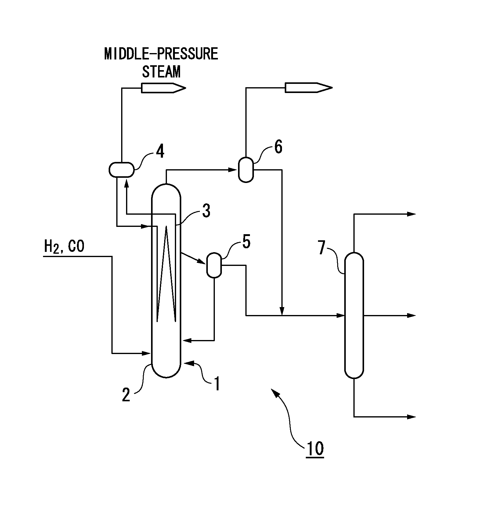
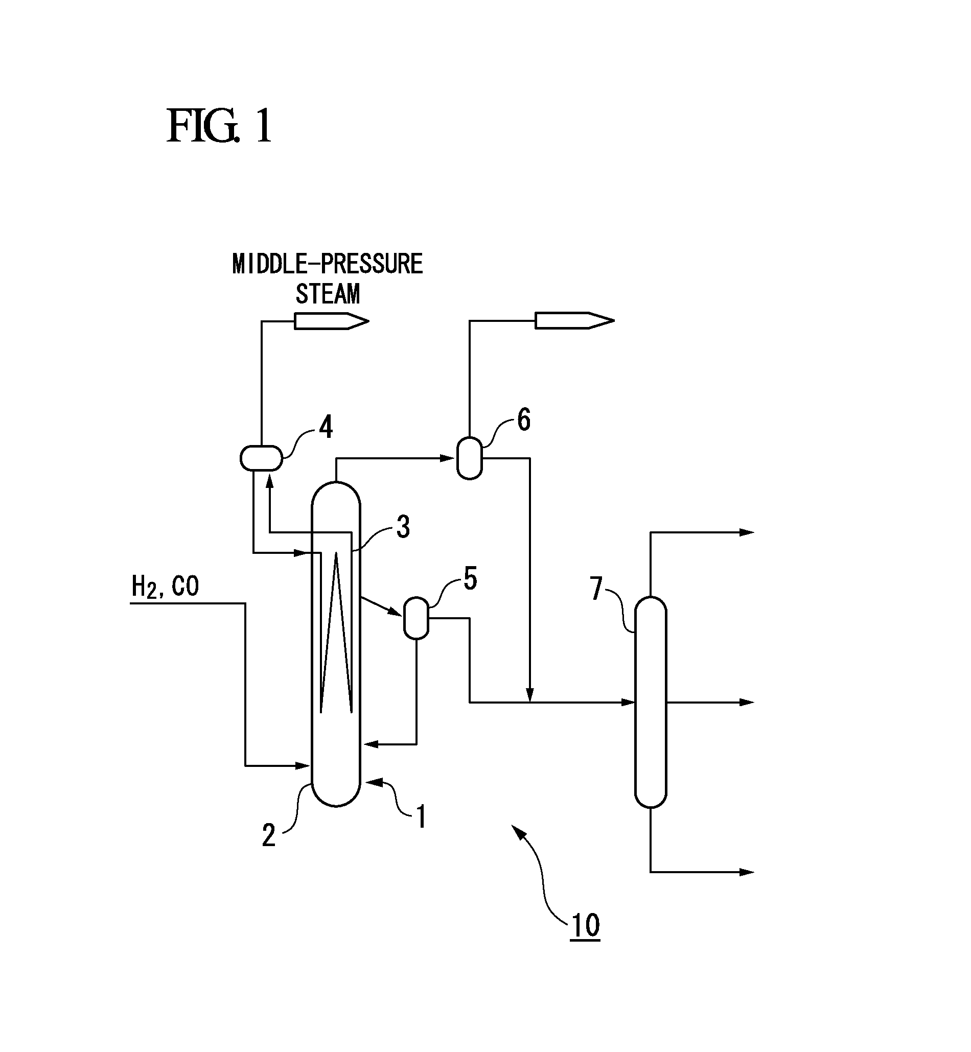
Image

Examples
example 1
[0083](Catalyst Preparation)
[0084]30 g of spherical silica particles (average pore size: 10 nm, average particle size: 70 μm) was weighed into a 250 ml glass bottle, 100 ml of an aqueous solution of nitric acid having a pH of 6.6 was added to the bottle, and the mixture was irradiated with ultrasound for 10 minutes at 40° C. Subsequently, approximately 50 ml of the supernatant liquid was removed using a Pasteur pipette, 150 ml of an aqueous solution of ammonium tricarbonatozirconate having a concentration of 0.3 mol / L was added to the bottle, and the bottle was left to stand for 24 hours at room temperature. The mixture was then filtered using a filter paper to collect (separate) the zirconium-supporting silica particles, and these particles were washed repeatedly with ion-exchanged water until the pH of the filtrate reached a value of 7. The particles were dried under vacuum, and then calcined under an air atmosphere, yielding a catalyst support. The zirconium oxide content, based ...
example 2
[0088]With the exception of altering the temperature of the reduction treatment used for obtaining the activated FT synthesis catalyst from the FT synthesis catalyst to 330° C., an activated FT synthesis catalyst was produced in the same manner as that described for example 1. Using this activated FT synthesis catalyst, an FT synthesis reaction was then conducted in the same manner as example 1. The results are shown in Table 1.
example 3
[0089]With the exception of altering the concentration of the aqueous solution of ammonium tricarbonatozirconate used when supporting ammonium tricarbonatozirconate on the silica particles so that the amount of supported zirconium oxide, based on the mass of the catalyst support, was 7.9% by mass, an activated FT synthesis catalyst was produced in the same manner as that described for example 1. Using this activated FT synthesis catalyst, an FT synthesis reaction was then conducted in the same manner as example 1. The results are shown in Table 1.
PUM
| Property | Measurement | Unit |
|---|---|---|
| Temperature | aaaaa | aaaaa |
| Fraction | aaaaa | aaaaa |
| Percent by mass | aaaaa | aaaaa |
Abstract
Description
Claims
Application Information