Second,
conductive materials present an opportunity for eddy currents to form, which currents generate heat that adversely affects patient safety and degrade the
scanner performance by field
distortion.
Fourth, the incompatible
implant material can potentially cause serious internal injuries to the patient.
Obviously the surrounding tissue adjacent the implantable device will be damaged in this case and the health of the patient will be compromised.
In addition, metallic components can become hot and burn the patient.
Due to MRI field induced torque and movement of the
implanted device, its components may become disconnected making the device inoperable.
Ferrites and other ferromagnetic material in
transformer cores, inductors and other electronic components become saturated, thereby jeopardizing the function of the
medical device.
Heating causes electronic components to operate out of specification.
This movement can be unsafe for the surrounding tissue.
The eddy currents may be strong enough to damage electronic circuits and destroy the implanted device.
The induced voltages and currents create locally very strong E-fields, in particular at the ends of the electrical, which can burn the patient.
Non-metallic implantable devices do not have these issues, but can still distort the uniformity of the
RF field if the
permittivity of the device is different than that of the surrounding tissue.
This distortion is especially strong at radio frequencies above 100 MHz.
This includes connections that become unsoldered due to the heat.
The device may generate pulsed voltages at unwanted times and locations in the leads of a
cardiac pacemaker.
Local distortion of the uniformity of the B-field component of the
RF field will give rise to
flip angle variation and creates contrast and signal-to-
noise ratio (SNR) inhomogeneity.
Choice of a plating material can degrade performance (increase attenuation) if its
bulk resistivity is greater than that of the body of the wire.
If such a conductor is placed inside the E field of an MRI RF transmit coil, there will be RF energy deposition in the tissue surrounding the wire resulting in elevated temperatures that may result in physical injury to the patient.
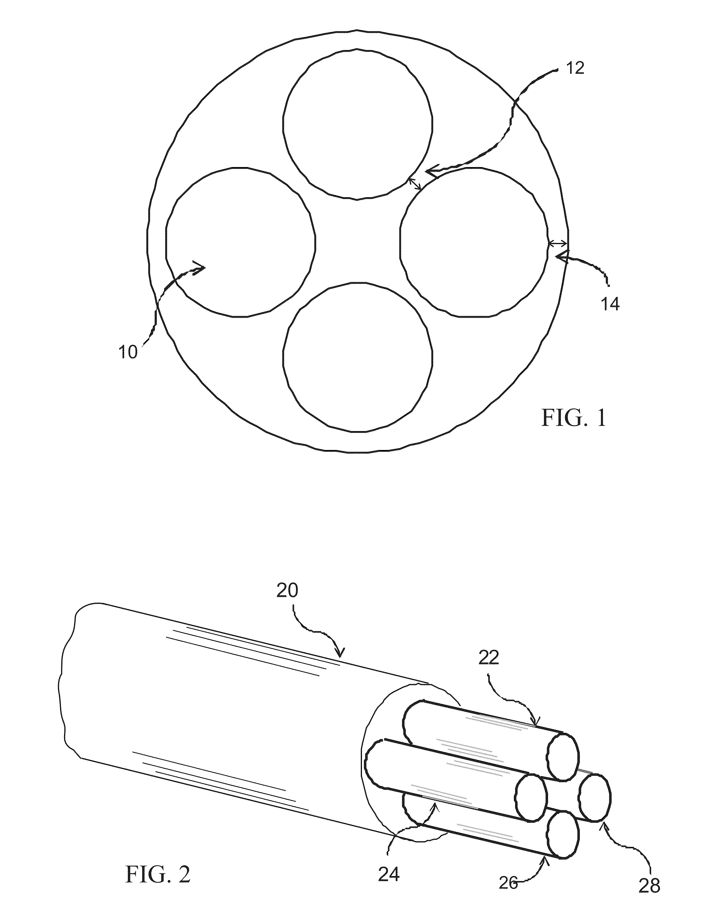
Various types of multi-lumen implantable leads have been suggested in prior art, however, these designs contain straight wires, straight stranded cables or very small coiled wires, which are not suitable for
MRI compatibility.
As discussed above, conductors, whether they are
solid or stranded construction, may result in high E-fields at the conductor end or can be prone to hotspots partway along the lead body if
resonance occurs from the induced MRI scanner's RF energy, which in turn result in elevated tissue temperatures that can be potentially injurious to the patient.
Small coils that can be easily distorted when compressed, stretched, or flexed, as would occur
in vivo as a result of (for example) movement or trauma, cannot maintain the close dimensional and electrical parameters that are necessary for
MRI compatibility.
Nevertheless this requirement and desirable lead
diameter (usually nine French or less) can be met with the proposed solution, while difficult if not impractical with the other solutions.

