BEOL integration scheme for copper CMP to prevent dendrite formation

a copper and copper-based technology, applied in the manufacture of basic electric elements, semiconductor/solid-state device manufacturing, electric devices, etc., can solve the problems of limiting the size reducing the cross-sectional area and significant electrical resistance of conductive contact elements

Active Publication Date: 2014-03-06
GLOBALFOUNDRIES US INC
View PDF7 Cites 10 Cited by
  • Summary
  • Abstract
  • Description
  • Claims
  • Application Information

AI Technical Summary

Benefits of technology

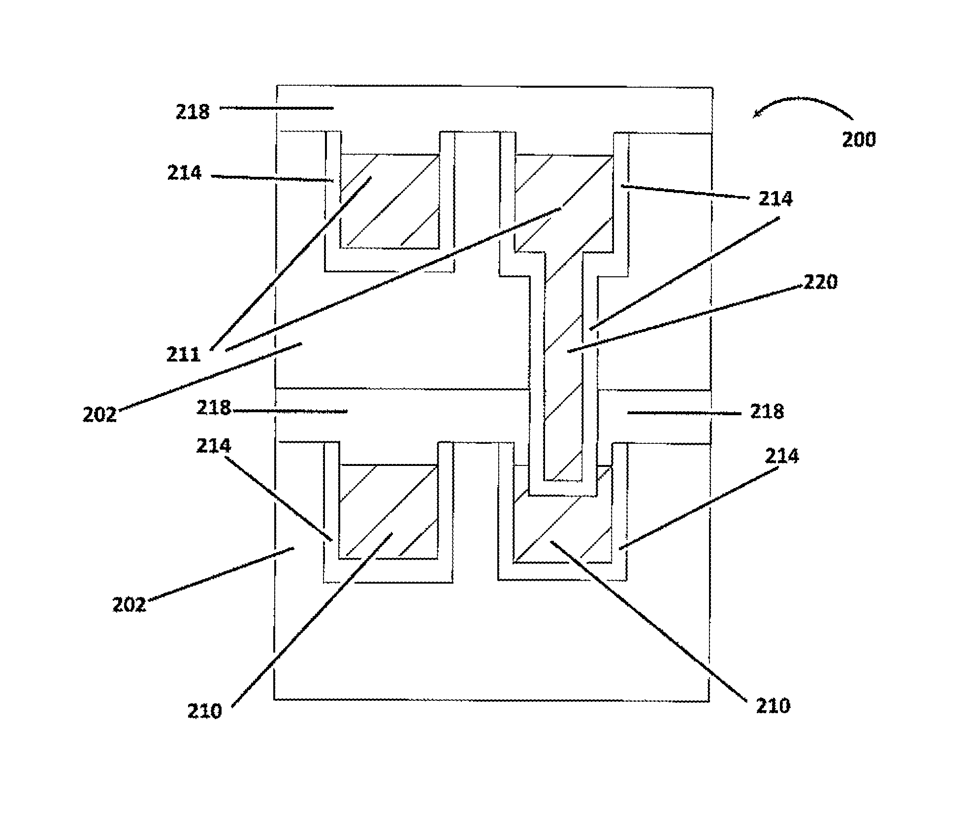
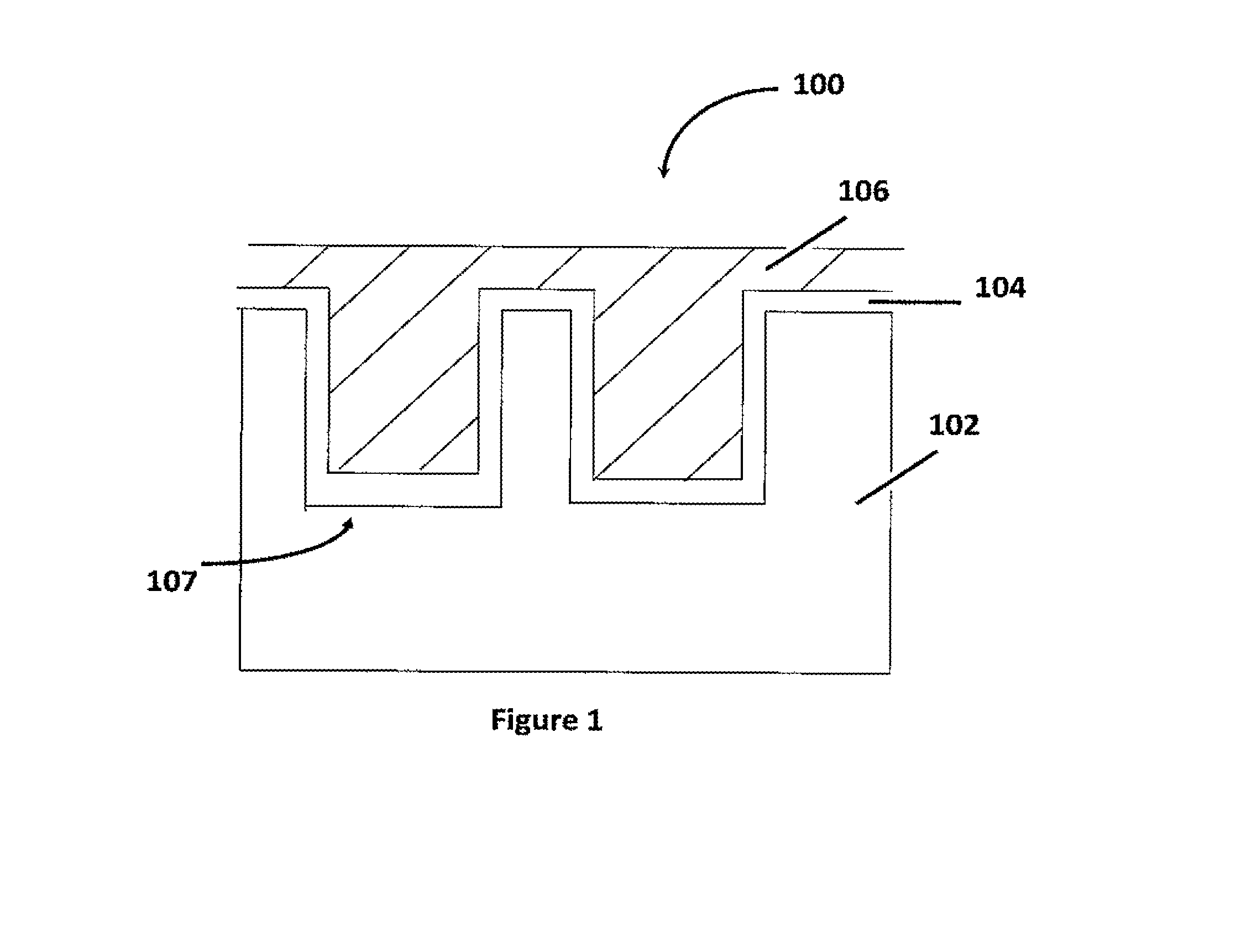
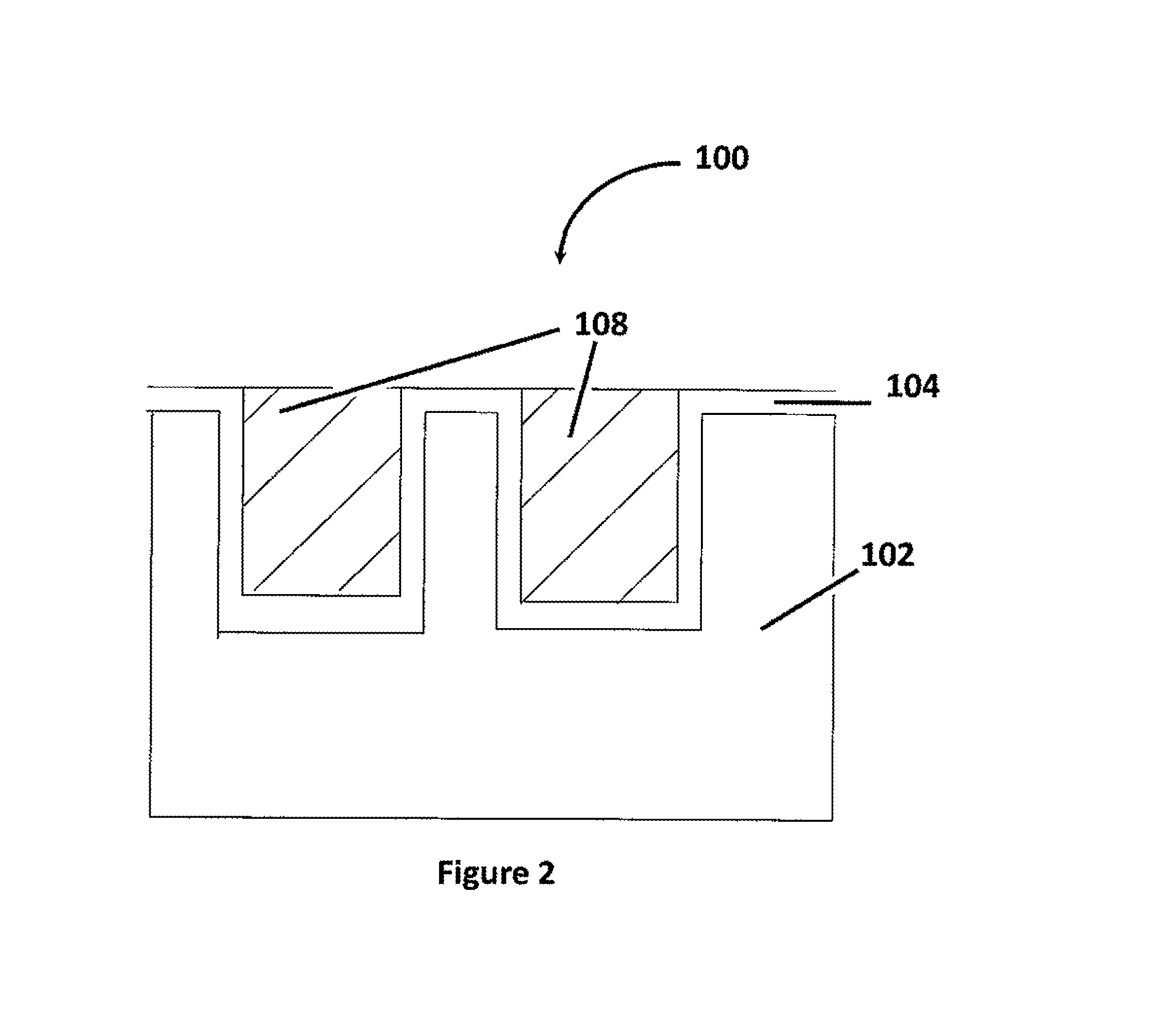
[0014]The proposed approach is an alternative CMP integration scheme that will eliminate the exposure of copper to ILD during CMP. This approach will prevent any dendrite formation. The approach can be used for all metal layers in BEOL stack. This approach can be utilized for multiple layers, as necessary, whenever copper CMP is desired.

Problems solved by technology

However, the ongoing shrinkage of feature sizes on transistor devices causes certain problems that may at least partially offset the advantages that may be obtained by reduction of the device features.
Upon decreasing channel length, however, the pitch between adjacent transistors likewise decreases, thereby limiting the size of the conductive contact elements—e.g., those elements that provide electrical connection to the transistor, such as contact vias and the like—that may fit within the available real estate between adjacent transistors.
Accordingly, the electrical resistance of conductive contact elements becomes a significant issue in the overall transistor design, since the cross-sectional area of these elements is correspondingly decreased.
However, the use of copper metallization systems with such low-k dielectric materials can be problematic.
This residual copper can result in formation of dendrites due to copper oxidation.
The presence of water will accelerate the dendrite growth which becomes a bigger problem for low-k ILD because it is porous and holds moisture.
The dendrite can result in connecting copper lines resulting in shorting, capacitance and Time Dependent Dielectric Breakdown (TDDB) issues.
However, the queue time needs to be short, for example less than 6 hours.
However, the short queue time needed is not ideal or practical for high volume manufacturing.
However, the use of such chemicals adds steps, complexity and cost to the manufacturing process.

Method used


Image

  • BEOL integration scheme for copper CMP to prevent dendrite formation
  • BEOL integration scheme for copper CMP to prevent dendrite formation
  • BEOL integration scheme for copper CMP to prevent dendrite formation

Examples


Embodiment Construction

[0019]Various illustrative embodiments of the invention are described below. In the interest of clarity, not all features of an actual implementation are described in this specification. It will of course be appreciated that in the development of any such actual embodiment, numerous implementation-specific decisions must be made to achieve the developers' specific goals, such as compliance with system-related and business-related constraints, which will vary from one implementation to another. Moreover, it will be appreciated that such a development effort might be complex and time-consuming, but would nevertheless be a routine undertaking for those of ordinary skill in the art having the benefit of this disclosure.

[0020]The present subject matter will now be described with reference to the attached figures. Various structures, systems and devices are schematically depicted in the drawings for purposes of explanation only and so as to not obscure the present disclosure with details ...


PUM

PropertyMeasurementUnit
thicknessaaaaaaaaaa
dielectric constantaaaaaaaaaa
queue timeaaaaaaaaaa

Abstract

Disclosed herein are various methods of forming copper-based conductive structures on integrated circuit devices by performing a copper deposition process to fill the trench or via with copper, which can be performed by fill, plating or electroless deposition. Copper clearing of copper overburden is performed using CMP to stop on an existing liner. Copper in the trenches or vias is recessed by controlled etch. An Nblok cap layer is deposited to cap the trenches or vias so that copper is not exposed to ILD. Nblok overburden and adjacent liner is then removed by CMP. Nblok cap layer is then deposited. The proposed approach is an alternative CMP integration scheme that will eliminate the exposure of copper to ILD during CMP, will prevent any dendrite formation, can be used for all metal layers in BEOL stack, and can be utilized for multiple layers, as necessary, whenever copper CMP is desired.

Description

BACKGROUND OF THE INVENTION[0001]1. Field of the Invention[0002]Generally, the present disclosure relates to the manufacture of sophisticated semiconductor devices, and, more specifically, to various methods of forming copper-based conductive structures using a chemical mechanical planarization (CMP) integration scheme that eliminates exposure of copper to interlayer dielectric (ILD).[0003]2. Description of the Related Art[0004]The fabrication of advanced integrated circuits, such as CPU's, storage devices, ASIC's (application specific integrated circuits) and the like, requires the formation of a large number of circuit elements in a given chip area according to a specified circuit layout. Field effect transistors (NMOS and PMOS transistors) represent one important type of circuit element that, to a great extent, substantially determines the performance capability of integrated circuit devices employing such transistors. A field effect transistor, irrespective of whether an NMOS tr...

Claims


Application Information

Patent Timeline
Patent Type & Authority Applications(United States)
IPC IPC(8): H01L21/768
CPCH01L21/7684H01L21/76832H01L21/76834
Inventor TANWAR, KUNALJEET
Owner GLOBALFOUNDRIES US INC
Why Eureka
Try Eureka