Battery plate with multiple tabs and mixed pore diameters

Inactive Publication Date: 2014-03-27
FIREFLY ENERGY INC
View PDF5 Cites 2 Cited by
  • Summary
  • Abstract
  • Description
  • Claims
  • Application Information

AI Technical Summary

Benefits of technology

The invention is an improvement to traditional lead acid batteries by changing the tab location and cell arrangement. This allows two cells in the battery to be connected in series, which leads to better performance and reduced maintenance issues. The method of manufacturing the battery is also provided. Overall, the design of the battery is easier to produce and results in a more powerful and durable battery.

Problems solved by technology

In a traditional design, the electroactivity between the plates and electrolyte is uneven, with some areas having high electroactivity and some low.
Areas of low electroactivity do not produce power and are thus undesirable.
This battery presented potential drawbacks such as shorts from loose conductive fibers, intercell leaks and negative grid corrosion.
This design, however, is difficult to manufacture.
Such designs are sensitive to the length of the cabling needed to connect the terminals since terminals are arising from both ends of the battery.
The end that needs the longest cable will have a higher resistance path and thus negate much of the improvement in electroactivity between the plates.
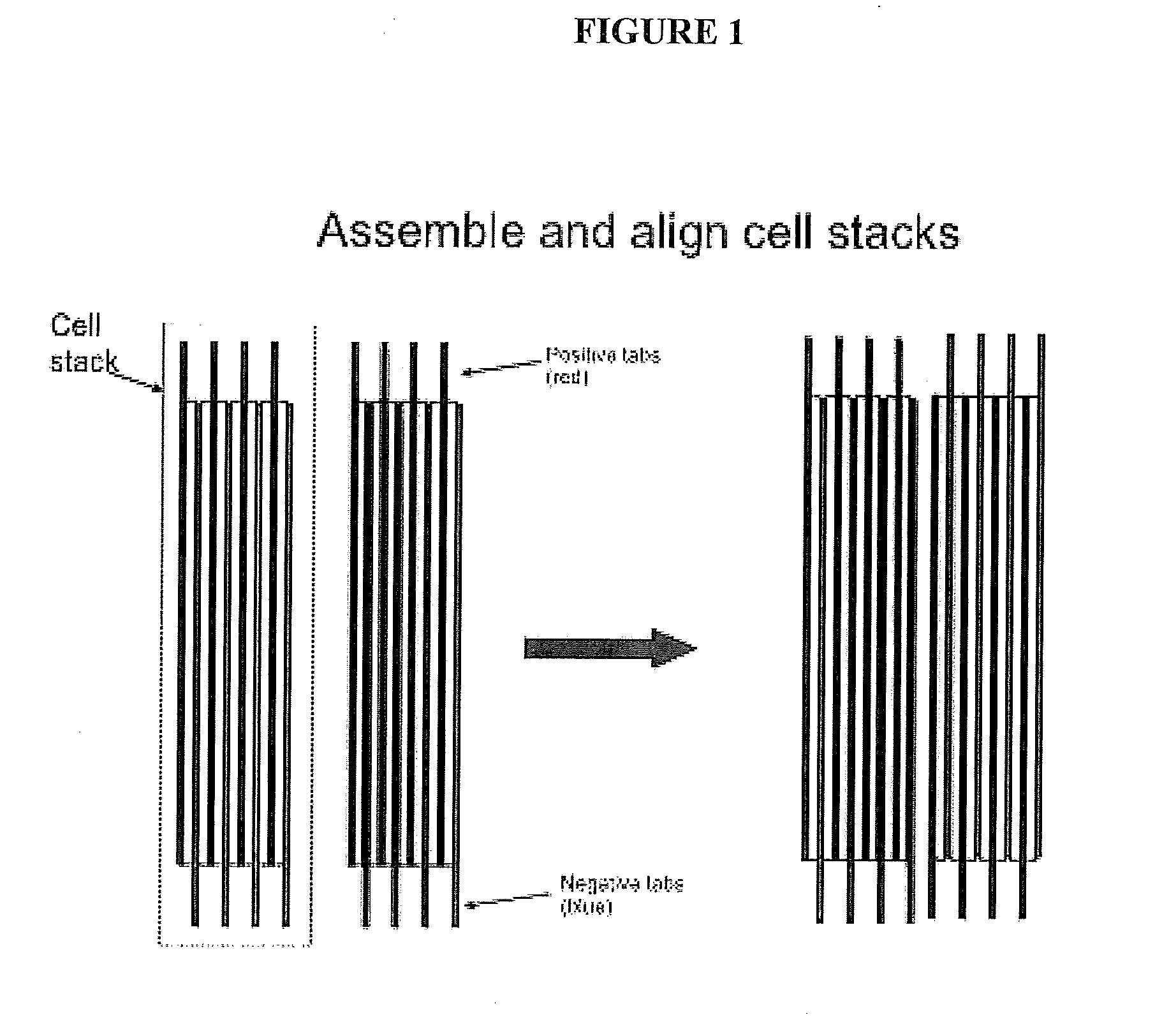
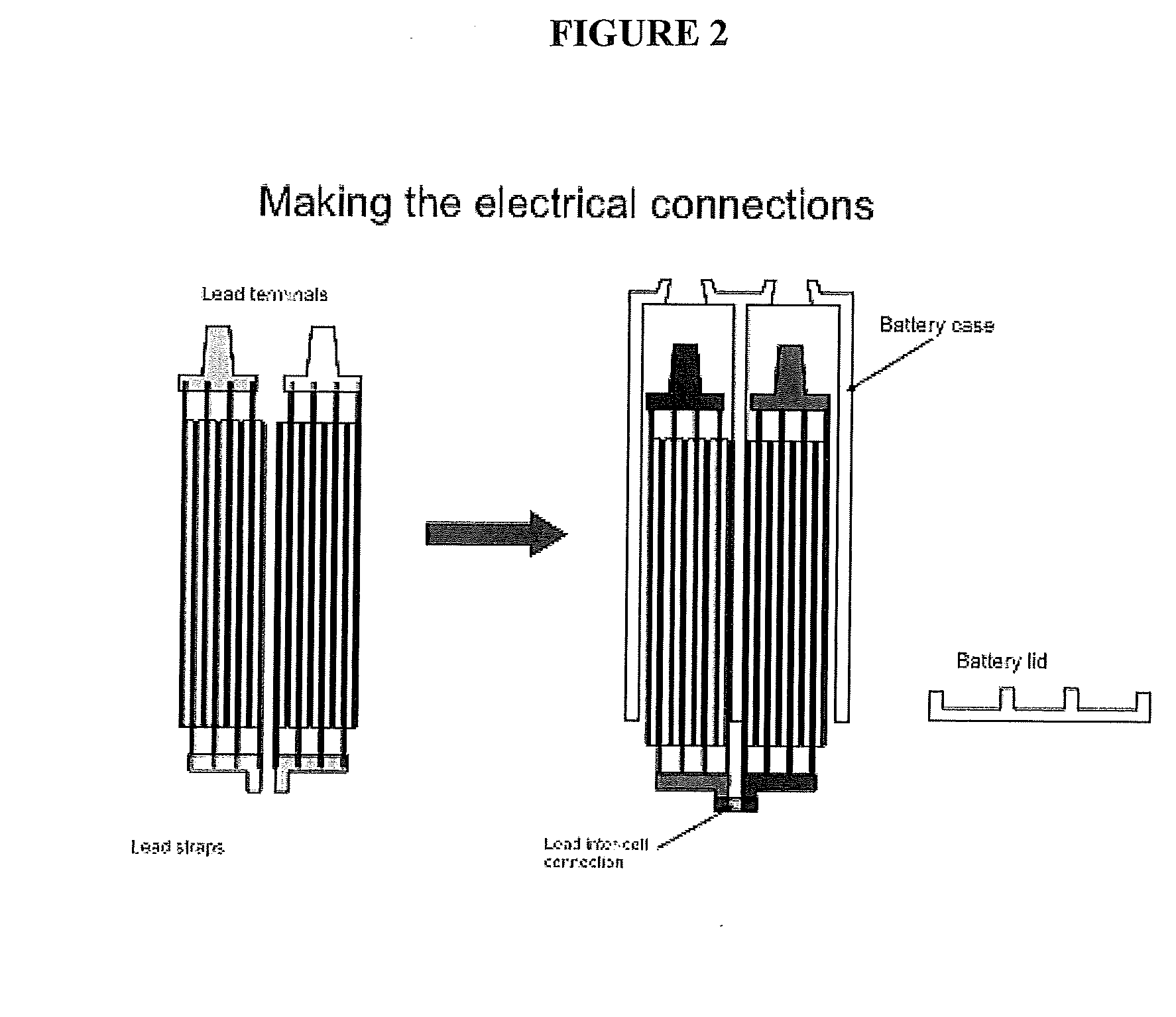
While promising, opposing tab batteries also proved to be more costly to manufacture due to the complexity of the connections, which in turn required more complex battery cases with a greater number of the seals that are required for a sealed lead acid battery.
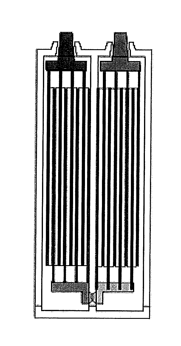
1. The battery terminals are on opposite sides of the battery making connection difficult;
2. Terminals on opposite sides of the battery make sealing more complex because of the increased complexity of the case;
3. Efforts to route the battery terminals to the same side of the battery greatly increases cost, size, and weight;
4. Opposing terminal batteries have required an investment in new equipment specific to their processing;
5. Battery terminals on opposite ends of the battery are non-standard, making the end-user also invest in new racking system design; and
6. Opposing tab batteries have only been for individual 2V cells, which increases cost to higher voltage systems.
Lead-acid batteries now use small pores, and great effort (both process and chemistry) is put into mixing active-material that is packed around the electrode to create this small network of pores.
This reaction is the creation of lead sulfates, which are quite large and tend to block the movement of more electrolytes deeper into the plates.
This well known surface sulfation problem is familiar to the layman as the tendency of auto batteries to crank the engine well on a first start attempt, followed by progressively weaker cranking by the battery with further start attempts if the engine does not start at first.
Electrolyte surface-tension and material surface energies are difficult to modify without adversely affecting battery function.
It was believed from past experience with gel electrolytes in batteries discussed in publications, that the gel particles create a tortuous path that slows ion-mobility between plates, and that this reduces high-rate discharge capacity considerably from non-gelled-electrolyte batteries.
“Gel Cell Batteries do not offer the same power capacity as do the same physical size AGM battery.
However, the Gel Cell excels in slow discharge rates and slightly higher operating temperatures and with excellent deep cycle capability.” from http: / / www.atbatt.com; “Gel is an older technology than RBSM technology for valve regulated lead acid batteries: gel batteries have been around for many years but have not been widely used except for special applications.
The gel system has an inferior performance at high discharge rates, therefore it is not suitable for applications such as SLI requiring a high rate discharge capability.” From: A guide to VRLA Battery Formation Techniques by Mike Weighall and Bob Nelson; “ABSORBED GLASS MAT BATTERIES: These are state of the art batteries.
Unfortunately this electrolyte thickening decreases the mobility of the ions which results in increased internal resistance.” From Oddmix.com.
Battery plates with a substantial number of large open pores, larger than about a 50 microns minor diameter, have difficulty retaining electrolytes in the large pores.
Even if initially filled with electrolytes, once the pore is emptied thru gassing or drying, there is generally insufficient capillary attraction to refill the pore.
Once dry they are unlikely to refill.
And once empty, battery capacity tends to drop.

Method used


Image

  • Battery plate with multiple tabs and mixed pore diameters
  • Battery plate with multiple tabs and mixed pore diameters
  • Battery plate with multiple tabs and mixed pore diameters

Examples


Embodiment Construction

[0041]The following description of the preferred embodiment(s) is merely exemplary in nature and is in no way intended to limit the invention, its application, or uses.

Tabs

[0042]FIGS. 5(a), 5(b) and 6 illustrate and explain the battery of the invention.

[0043]FIG. 5a represents two assembled cells 50, 52 (each comprising positive 54 and negative 56 plates separated by a separator 58 that are attached together for each cell, and the cells are arranged with opposing tabs. The two terminal posts 60, 62 (one on each cell) protrude at the bottom. The connection between the cells 64 (the bus) is across the top and is made, in this instance, by a casting lead-metal from the positive tabs of one cell to the negative tabs of the adjacent cell. It is intended that the scope of the present invention will include any method of forming this connection now known or hereinafter devised.

[0044]FIG. 5(b) further shows the container walls 66 and inter-cell wall 68, which are manufactured according to s...


PUM


Abstract

A battery electrode assembly comprises a porous electrode plate having a plurality of large and small pores, a pore insert within a plurality of pores, the pore insert maintaining an electrolyte in the pores substantially throughout a discharge / charge cycle. The pore insert may be a gelled electrolyte. The pore insert may be a particulate material. The electrodes may be used in a battery having cells with opposing positive and negative tabs connected in series by an intercell connector.

Description

CROSS REFERENCE TO RELATED APPLICATIONS[0001]This application is a U.S. National Phase Application of International Application No. PCT / US2012 / 26350 filed Feb. 23, 2012, which claims priority to U.S. provisional applications 61 / 446,403 filed Feb. 24, 2011 and 61 / 535,434 filed Sep. 16, 2011, and both of which are incorporated herein by reference.BACKGROUND OF THE INVENTION[0002]1. Field of the Invention[0003]The present invention is in the field of lead acid batteries, and in particular the arrangement of tabs for multi-cell lead acid batteries and also batteries having multiple pore sizes, and methods of manufacturing the same.[0004]2. Related Art[0005]Traditionally, valve-regulated lead acid (“VRLA”) batteries have positive and negative plates each plate having at least one tab, which plates are separated using a separator, surrounded by electrolytic material and sealed to make the battery, with tabs of varying numbers located in various arrangements, which tabs are connected to on...

Claims


Application Information

Patent Timeline
IPC IPC(8): H01M10/10
CPCH01M10/10H01M4/80H01M10/0413H01M10/121H01M10/14Y02E60/10Y02P70/50
Inventor KELLEY, KURTIS C.BHANDARI, MUKESHSTONE, MATHEW
Owner FIREFLY ENERGY INC
Why Eureka
Try Eureka