
Functional-imaging-based ablation monitoring

a technology of ablation monitoring and functional imaging, applied in the field of functional imaging-based ablation monitoring, can solve the problems of serious consequences for patients, under- or overheating of the site, and tissue is not sufficiently coagulated, and achieve the effect of improving data magnitud

Inactive Publication Date: 2014-03-27
KONINKLIJKE PHILIPS ELECTRONICS NV
View PDF2 Cites 17 Cited by
  • Summary
  • Abstract
  • Description
  • Claims
  • Application Information

AI Technical Summary

Benefits of technology

The patent describes a technology that allows real-time monitoring of a procedure called RF cardiac ablation, which is used to treat heart rhythm disorders. The technology uses a display to show the signal that is generated during the procedure, which helps to better understand the physiology of the heart. This approach also improves the detection of abnormal blood flow patterns in the area around the heart.

Problems solved by technology

One major challenge of RF ablation is to actively control the ablation settings during treatment.
Although a highly-skilled therapist is able to achieve successes with this approach, it is not always the case, and there are serious consequences for the patient when an error is made.
The two major therapy-related problems result from either the under- or over-heating of the site.
In the case of under-heating, the tissue is not sufficiently coagulated or the ablation lesion is not deep enough to form the arrhythmia-blocking lesion desired by the therapist.
This can lead to persistent or recurring symptoms in the patient, and the requirement for subsequent treatment(s), longer periods of hospitalization, and greater risks of stroke and embolism.
Redo ablation procedures are more difficult to perform, since the already treated areas are very hard to discriminate from insufficiently treated ones.
The other extreme, over-heating, either causes rupturing of the tissue at the treatment site, releasing potentially life-threatening particles into the blood stream, or causes damage to neighboring organs and tissues.
In the case where other organs are affected, fistulas can develop and these are often life-threatening (e.g., a fistula in the esophagus has roughly a 75% mortality rate).

Method used


Image

  • Functional-imaging-based ablation monitoring
  • Functional-imaging-based ablation monitoring
  • Functional-imaging-based ablation monitoring

Examples


Embodiment Construction

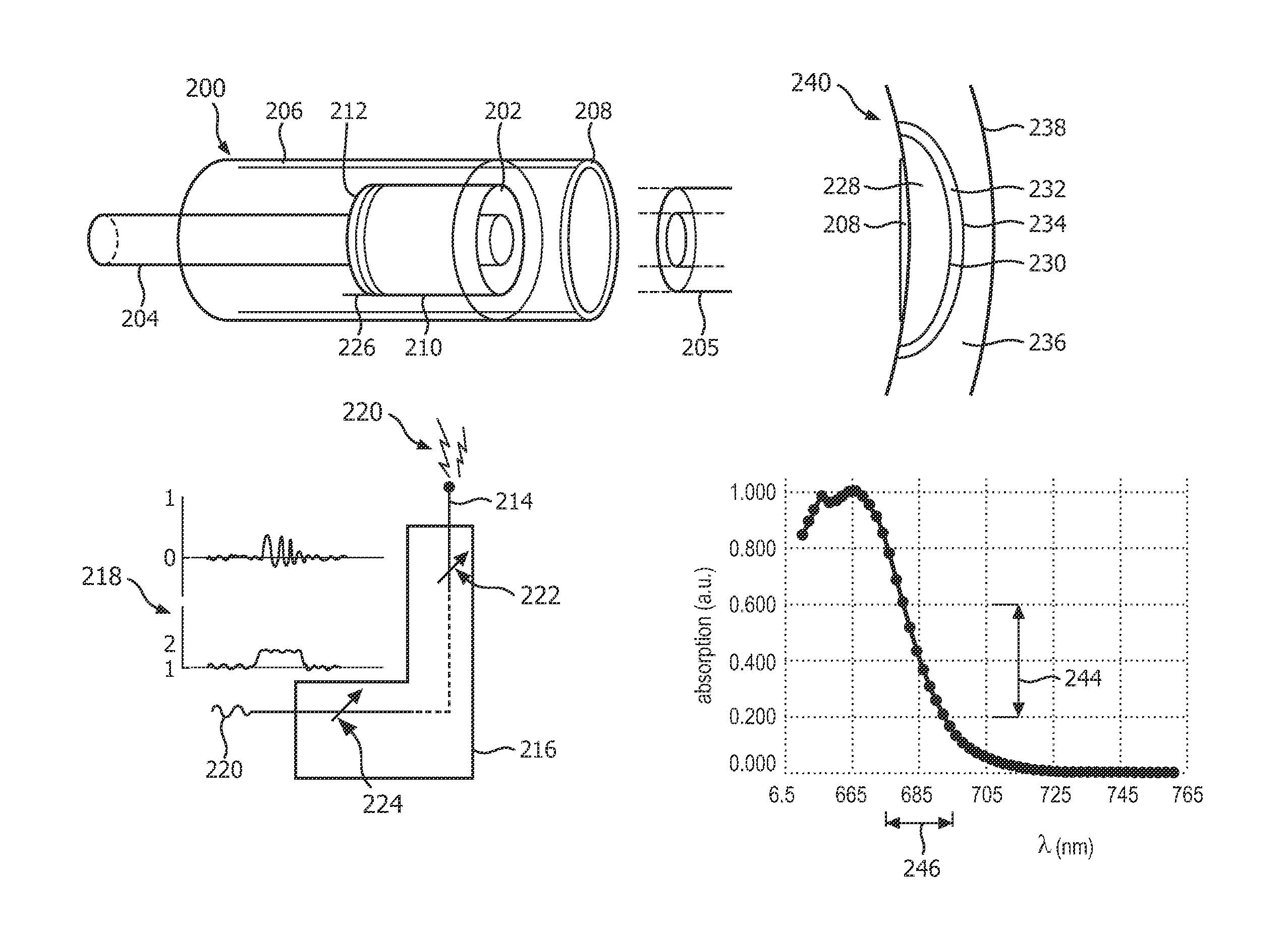
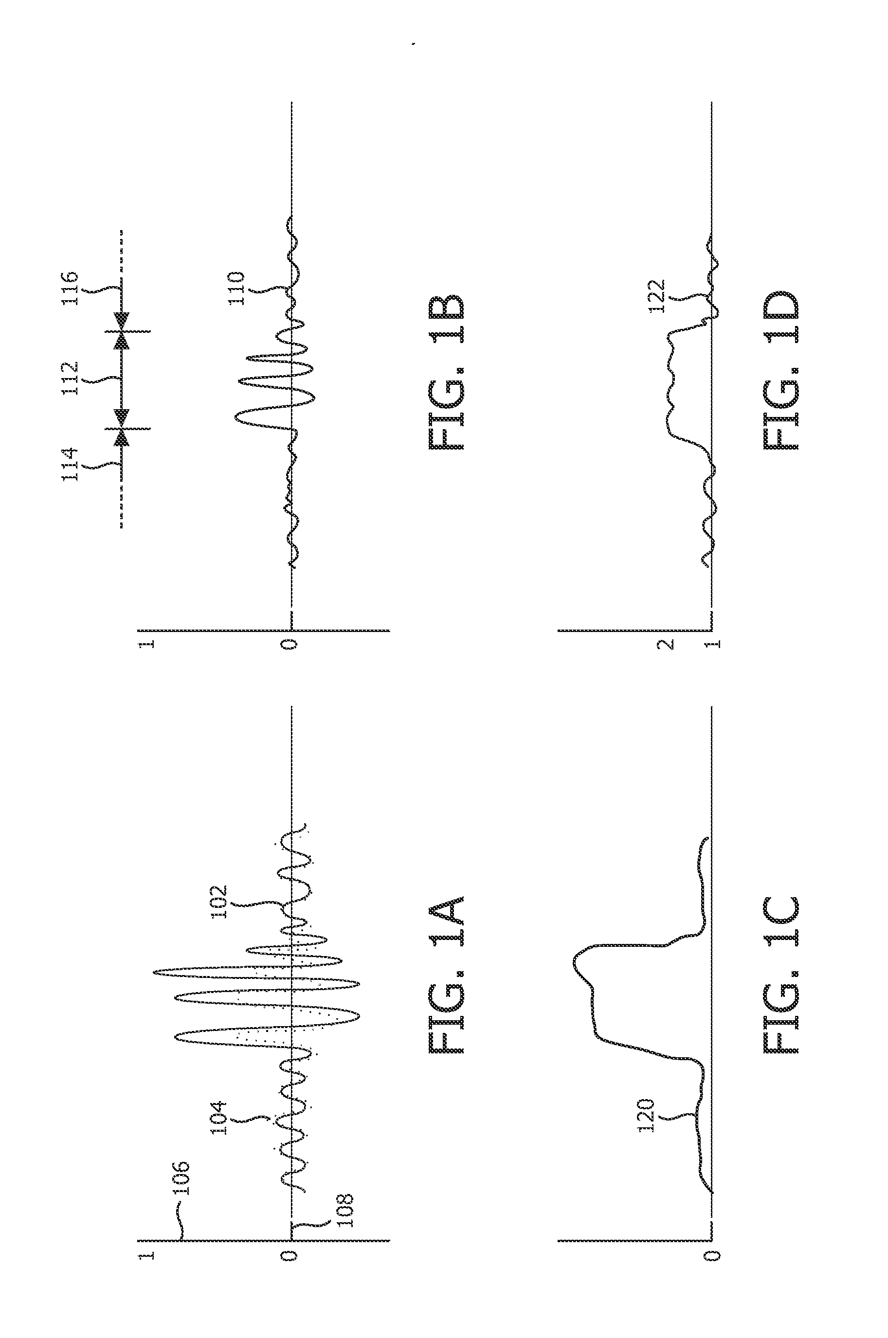
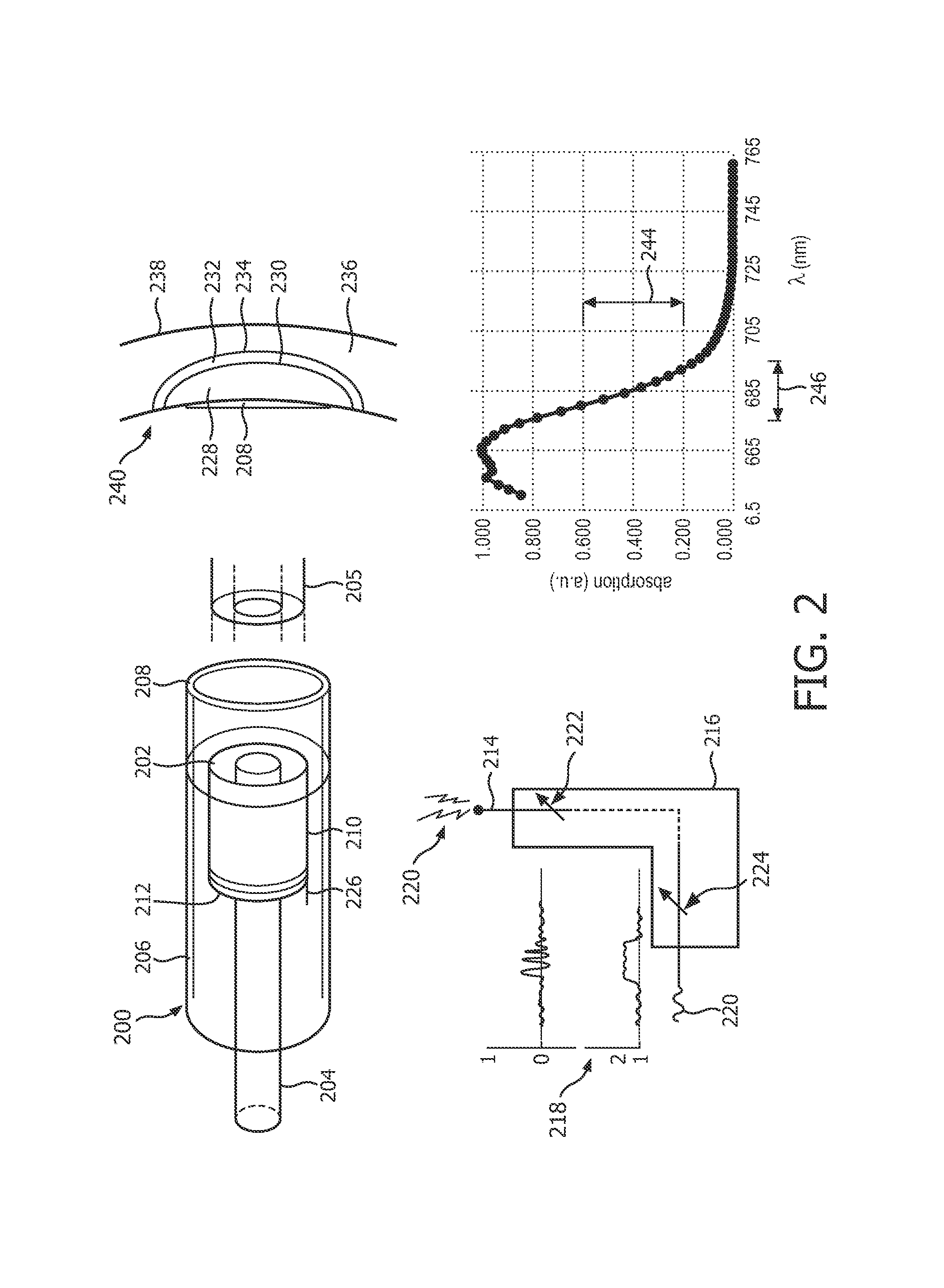
[0033]FIG. 1A depicts, approximately and for illustration purposes, two time waveforms, specifically RF waveforms, corresponding to photoacoustic absorption by biological tissue irradiated at two respective frequencies. The first waveform 102, generated by a first frequency of irradiation, or equivalently “wavelength”, is shown as a solid line or curve. The second waveform 104 for a second wavelength is shown as a dotted curve. A vertical scale 106 represents the amplitude of an acoustic wave. A horizontal scale 108 indicates time. With a single flash of a light source, a laser or near-infrared light-emitting diode (LED) for example, the light, as it propagates through biological tissue will in part be absorbed, may in part be reflected and may in part pass through. The absorbed energy causes heating, expansion, and, in response, an acoustic wave which can be detected and measured. Tissue with higher light absorption has an acoustic response of greater absolute magnitude. Tissue wit...


PUM


Abstract

Functional imaging for localization in biological tissue entails measuring a response in the tissue (240) to electromagnetic radiation. A catheter (200) for real-time monitoring of cardiac ablation is employed to distinguish a hemorrhage zone (232) from the sandwiching necrotic and healthy tissue, or to distinguish exogenous photoacoustic contrast agent from bordering native tissue. A pair of wavelengths is selected for differential absorption (244) of the radiation in, correspondingly, the hemorrhage zone or where the contrast agent exists, and relatively similar absorption elsewhere. Near infrared laser or LED light may be used photoacoustically to serially acquire (S310, S320) the two datasets to be compared, each representative of a time waveform. Alternatively, acquisition is for a pair of wavelength bands of microwave-induced thermoacoustic data. In either case, the members of the dataset pair are combined (110, 122) by subtraction or division to effect the piece-wise cancellation / enhancement for display (218) of the resulting signal in real time.

Description

FIELD OF THE INVENTION[0001]The present invention is directed to imaging for localization in biological tissue and, more particularly, to analyzing a response in the tissue to electromagnetic radiation.BACKGROUND OF THE INVENTION[0002]In the minimally-invasive treatment of cardiac arrhythmias, the radiofrequency (RF) ablation catheter is the most commonly-used therapy tool, and is referred to as the gold standard in trials of new ablation catheter designs. One major challenge of RF ablation is to actively control the ablation settings during treatment. Currently, the therapist relies on his or her own expertise to determine the optimal parameters for ablation, such as power, temperature, and duration. Note that these settings vary largely, due to sizable intra-patient differences of thickness of the local heart wall, perfusion, blood pressure and velocity, heart rhythm, etc. Although a highly-skilled therapist is able to achieve successes with this approach, it is not always the cas...

Claims


Application Information

Patent Timeline
IPC IPC(8): A61B5/00A61B18/18A61B18/14A61K49/00
CPCA61B5/4836A61K49/0002A61B18/18A61B2576/00A61B5/0059A61B18/1492A61B5/742A61B5/0044A61B5/0084A61B5/0095A61B5/6852A61B2018/00577A61B2090/378
Inventor RADULESCU, EMILHUANG, SHENG-WENERKAMP, RAMONJANKOVIC, LADISLAVSHI, YANSHAHZAD, KHALID
Owner KONINKLIJKE PHILIPS ELECTRONICS NV
Learn More