
Fabricating method of semiconductor chip

a technology of metal oxide semiconductor and fabrication method, which is applied in the manufacturing of semiconductor/solid-state devices, basic electric elements, electric devices, etc., can solve the problems of difficult to control the thickness of metal silicide layers, and reducing the resistance value of semiconductor devices. , to achieve the effect of enhancing the performance of the deep submicron mos

Inactive Publication Date: 2014-04-03
NAT APPLIED RES LAB
View PDF14 Cites 13 Cited by
  • Summary
  • Abstract
  • Description
  • Claims
  • Application Information

AI Technical Summary

Benefits of technology

The present invention provides a method for making a semiconductor chip with a very thin and low-resistance metal semiconductor compound layer. This method can simultaneously activate the source / drain region and repair the crystal lattice structure, which improves the performance of deep submicron MOSFET.

Problems solved by technology

With the miniaturization trends of the semiconductor devices in the deep submicron generation, it is an important issue to improve the device performance in the fabrication of the semiconductor devices.
For example, in a metal oxide semiconductor field effect transistor (MOSFET), the dopant for activating the source / drain region, the repairing of the damaged crystal lattice structure from dopant implantation or the simultaneous formation of metal silicides on the gate structure and the source / drain region may reduce the resistance value of the semiconductor device.
However, the conventional high temperature RTA process is detrimental to the production of the MOSFET with the size under the deep submicron.
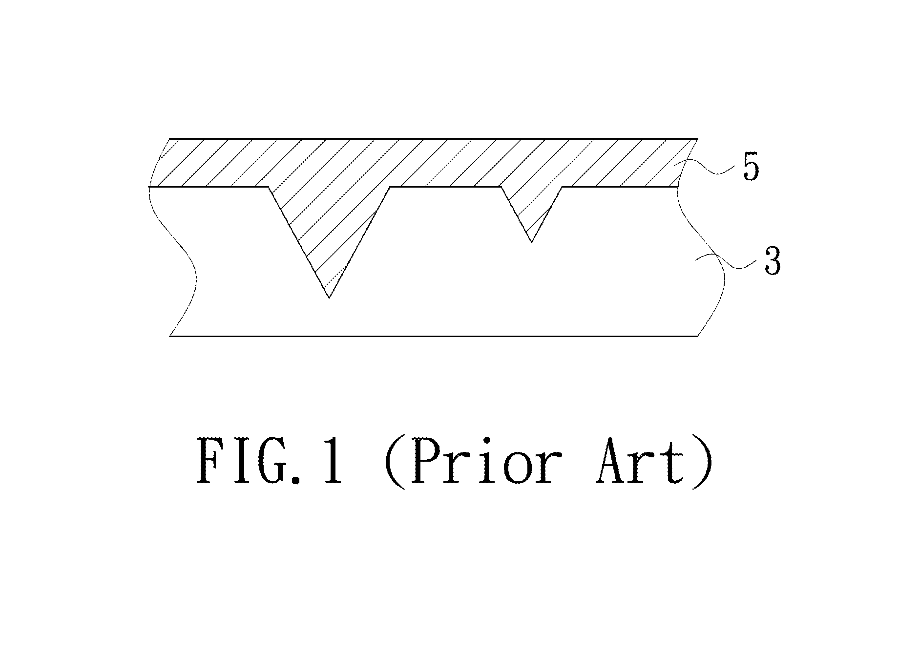
Under this circumstance, it is difficult to control the thickness of the metal silicide layer 5, and a source / drain leakage current is possibly generated.
In the conventional semiconductor manufacturing process, it is impossible to repair the crystal lattice structure of the source / drain region at the ultra-high temperature after the metal silicide layer is formed.
In other words, it is difficult to form an ultra-thin and low-resistance metal semiconductor compound layer by the conventional semiconductor manufacturing process.

Method used


Image

  • Fabricating method of semiconductor chip
  • Fabricating method of semiconductor chip
  • Fabricating method of semiconductor chip

Examples


Embodiment Construction

[0034]The present invention will now be described more specifically with reference to the following embodiments. It is to be noted that the following descriptions of preferred embodiments of this invention are presented herein for purpose of illustration and description only. It is not intended to be exhaustive or to be limited to the precise form disclosed.

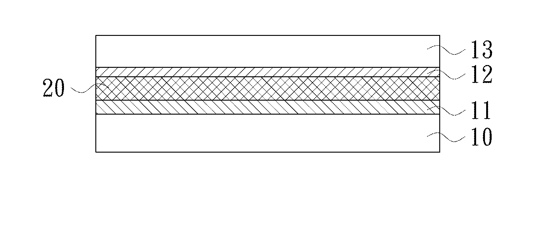
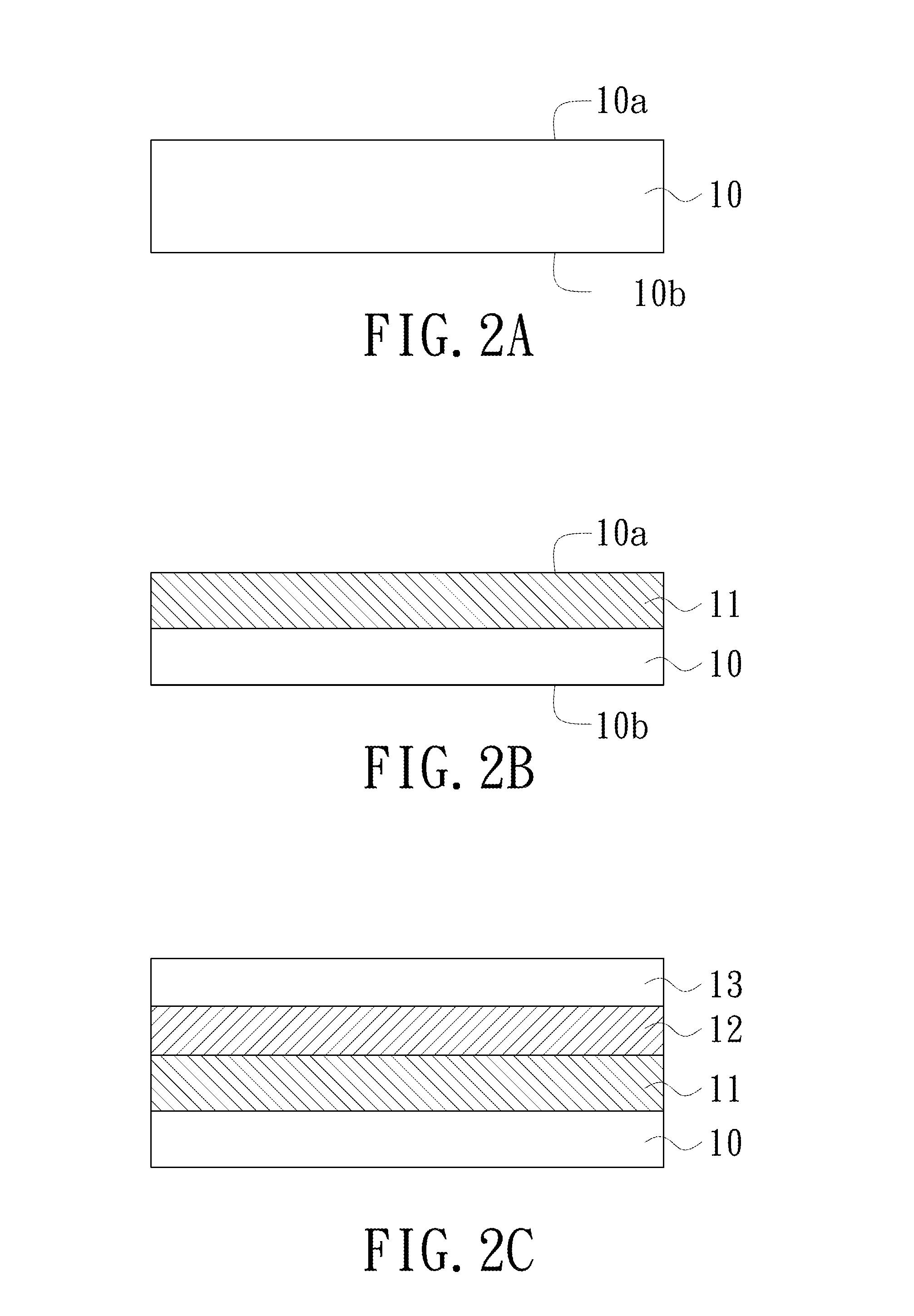
[0035]The present invention provides a fabricating method of a small-sized semiconductor chip. For example, the small-sized semiconductor chip is a deep submicron MOSFET. FIGS. 2A˜2F are schematic cross-sectional views illustrating a fabricating method of a semiconductor chip according to an embodiment of the present invention.

[0036]Firstly, as shown in FIG. 2A, a substrate 10 is provided. The substrate 10 is made of indium gallium arsenide, gallium arsenide, pure silicon, silicon germanium, carbon-doped silicon, phosphor-doped silicon, boron-doped silicon, carbon-doped germanium or tin-doped germanium. In addition, the substrate...


PUM


Abstract

A fabricating method of a semiconductor chip includes the following steps. Firstly, a substrate is provided, wherein an amorphous semiconductor layer is formed in a first surface of the substrate. Then, a first metal layer is formed on the amorphous semiconductor layer. Then, a thermal-treating process is performed to result in a chemical reaction between the first metal layer and a part of the amorphous semiconductor layer, thereby producing an amorphous metal semiconductor compound layer. Afterwards, a microwave annealing process is performed to recrystallize the amorphous metal semiconductor compound layer as a polycrystalline metal semiconductor compound layer.

Description

FIELD OF THE INVENTION [0001]The present invention relates to a fabricating method of a semiconductor chip, and particularly to a fabricating method of a metal oxide semiconductor transistor.BACKGROUND OF THE INVENTION [0002]With the miniaturization trends of the semiconductor devices in the deep submicron generation, it is an important issue to improve the device performance in the fabrication of the semiconductor devices. For example, in a metal oxide semiconductor field effect transistor (MOSFET), the dopant for activating the source / drain region, the repairing of the damaged crystal lattice structure from dopant implantation or the simultaneous formation of metal silicides on the gate structure and the source / drain region may reduce the resistance value of the semiconductor device. In other words, the activation number of the source / drain region and the resistance value of the metal silicides may influence the performance of the MOSFET.[0003]In the conventional semiconductor man...

Claims


Application Information

Patent Timeline
IPC IPC(8): H01L21/20
CPCH01L21/2022H01L21/28518
Inventor LEE, YAO-JENSUNG, PO-JUNGHEH, DA-WEIHOU, FU-JULO, CHIH-HUNGHSUEH, FU-KUOCHEN, HSIU-CHIH
Owner NAT APPLIED RES LAB
Learn More