Coated woodworking tool

a woodworking tool and coating technology, applied in the direction of manufacturing tools, superimposed coating process, flat surface machines, etc., can solve the problems of gumming of the blades, comb cracking, cutting edge chipping, etc., and achieve the effect of long service life of the coated tool

Inactive Publication Date: 2014-05-08
W BLOSCH
View PDF5 Cites 9 Cited by
  • Summary
  • Abstract
  • Description
  • Claims
  • Application Information

AI Technical Summary

Benefits of technology

[0027]As per the invention, a sliding layer containing sulphides, tellurides or selenides, in particular sulphides, tellurides or selenides having transition metals such as Mo, Nb or Ta, is deposited onto the hard material layer, which sliding layer is known for its advantageous tribological properties. Surprisingly it was found that a sliding layer as per the invention or solid lubricant layer respectively, for example, a molybdenum disulphide coating, leads to a significantly longer service life of the woodworking tool coated with said layer in spite of oxygen sensitivity and lower sublimation temperature. A possible reason for this surprising result is that the woodworking tool is heated far less than usual due to the friction-reducing coating. The chemical affinity between wood and the sulphur compounds used in the sliding layer could also play a role. The inventors also found to their surprise that the surface quality of wood workpieces, in particular solid wood workpieces, which had been cut using a cutting tool having a coating as per the invention, was considerably better than that of wood workpieces, which had been machined using conventional, uncoated cutting tools or tools with only a hard-material coating. The cutting tools used had the same cutting edge radii in both cases in terms of measurement accuracy, and consequently it could actually be expected that the result would be the same. Surprisingly it was not possible to achieve the same surface quality with woodworking tools, the blades of which were coated with a hard-material layer, as with cutting tools with a sliding layer as per the invention. The measurement of surface quality was performed subjectively by sweeping the palm of the hand over the machined wood. Comparative tests with various people showed that this way of measuring surface quality provided practical results. The cutting tools as per the invention are not only suitable for machining solid wood, but also glued wood such as chipboard or finger jointed, glued wood, which is particularly abrasive due to the adhesives it contains. The inventors also found to their surprise that when cutting wood using a woodworking tool as per the invention, approximately 25% fewer fine dust particles (particle size of <100 □m) were produced over the life of the tool.
[0030]Although it has been previously assumed that the cutting edge radius would increase by the thickness of the coating if a coating were applied, measurements showed that the cutting edge radius only increased slightly as a result of coating with a hard-material layer and a sliding layer as per the invention, although the cutting edge (in contrast to the teaching of DE-A-195 11 829) was also coated. It was possible to limit the cutting edge radius to less than 50%, less than 40% or less than 30% of the layer thicknesses applied to the rake face and / or flank face of the cutting tool. This has the advantage that a subsequent coating of the coated woodworking tool can be dispensed with.
[0031]Advantageously, the thickness of the hard-material layer of the coated woodworking tool on the rake face has a lower limit of 0.5 μm, 1 μm 1.5 μm, and an upper limit of 7 μm, 5 μm, or 3.5 μm. Tests have shown that a resharpening of the cutting edge can be avoided with such layer thicknesses and a long service life achieved. The hard-material layer consists preferably of compounds of metals in groups IVa, Va, VIa of the periodic table having the elements boron, carbon, nitrogen or oxygen. They may contain TiC, TiN, TiCN, TiAlN, WC, Al2O3, BC, SiC, VC, CrN, CrBN, CrCN, CrAlN, CrSiN, CrTiN, AlTiN, AlTiCrN, BN, ZrN, ZrCN, AlCrN, Ti2N, SixNy, or mixed compounds of two or a plurality of the above-mentioned materials as a substantial element or consist entirely of said materials.
[0038]Molybdenum disulphide can be formed here by the evaporation of molybdenum and simultaneous admission of a gas containing sulphur. Alternatively, an MoS2 target can be used and MoS2 sputtered on said target. The latter method may be preferred since the sliding layers produced using said method result in a long service life of the coated tool.

Problems solved by technology

This results in wear on the cutting surfaces, comb cracks, cutting edge chipping, plastic deformation, erosion of the cutting tip (crater wear) etc.
In contrast with metal working tools, wear in woodworking tools is caused primarily by wear, however corrosion and gumming of the blades also play a major role.
It is therefore obvious to a person skilled in the art that, due to the different requirements in respect of woodworking and metal working tools, knowledge from the manufacture of metal working tools is not easily transferred to woodworking tools.
The machined wood surface looks good at first, but when it is painted, the compressed fibres spring back up which produces an unusable result on the surface.
In addition, working with a blade that is no longer ‘sharp’ creates much more dust with a particle size<100 μm, since the fibres are broken apart, not cut.
Since woodworking tools are not cooled during the cutting process and therefore can become extremely hot, molybdenum disulphide has not been considered previously as a sliding layer for woodworking tools.
According to EP-A-2 279 837, corrosion resistance is one of the main problems in coated woodworking tools along with wear resistance.
The use of a solid lubricant layer consisting of MoS2 is advised against since it lacks the required hardness and adequate adhesive force.
This is not possible, however, when working with wood.

Method used


Image

  • Coated woodworking tool
  • Coated woodworking tool
  • Coated woodworking tool

Examples


exemplary embodiment 1

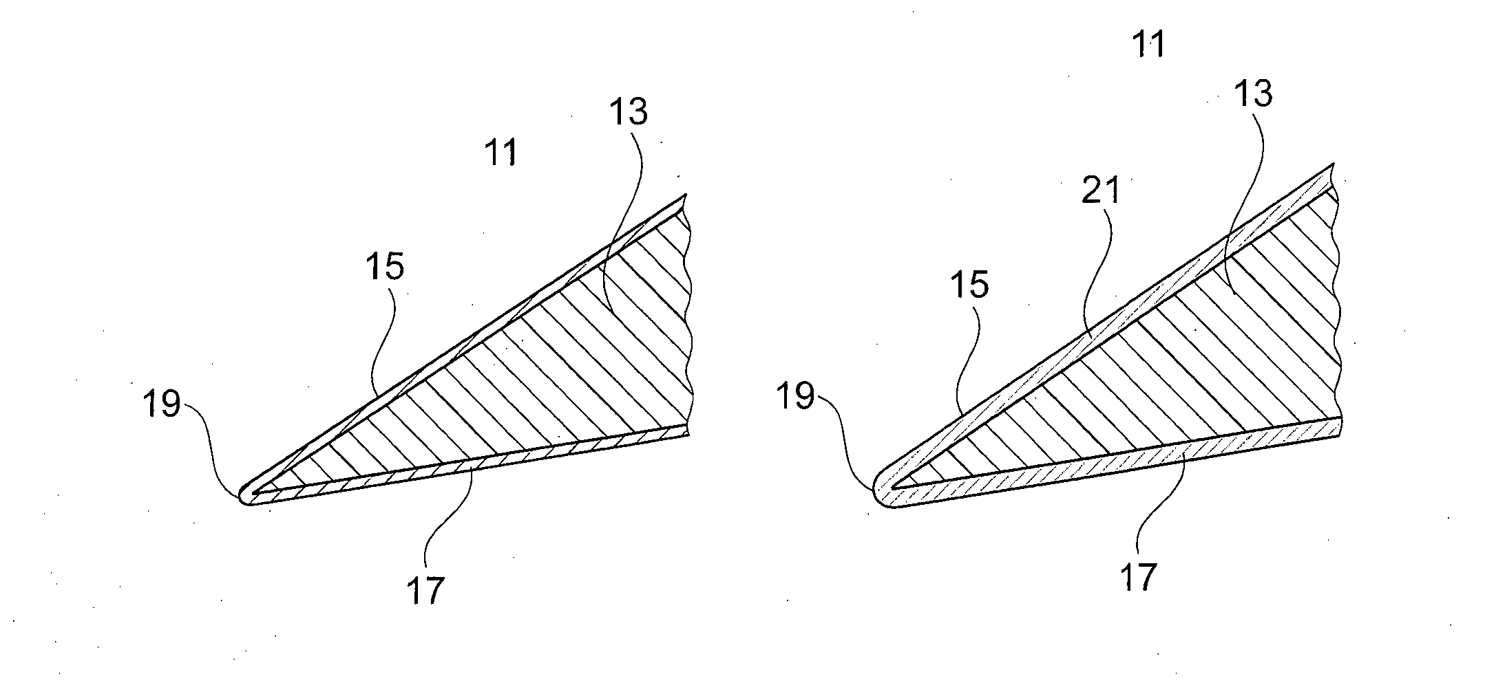
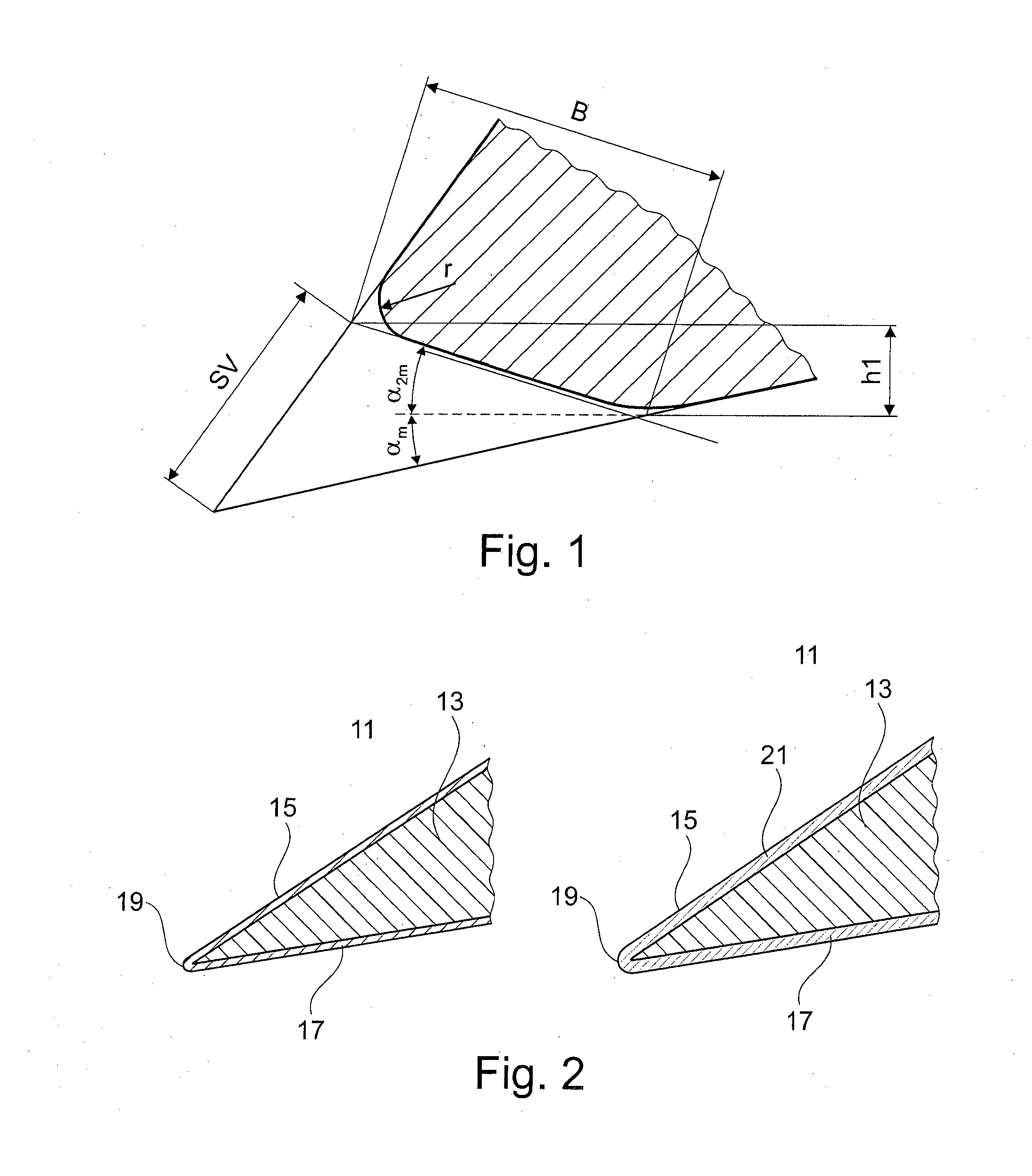
[0049]A woodworking tool A having a defined edge radius is coated by means of a generally known PVD arc method in a coating system as per EP 1 524 329 A1 or WO 0250865 with a base layer containing chromium, for example, CrN. The thickness of the CrN layer is between approx. 1 and 3 micrometres.

[0050]Molybdenum disulphide with a thickness of approx. 1 micrometre is then applied to the tool A in a further coating system by means of a generally known magnetron sputtering method.

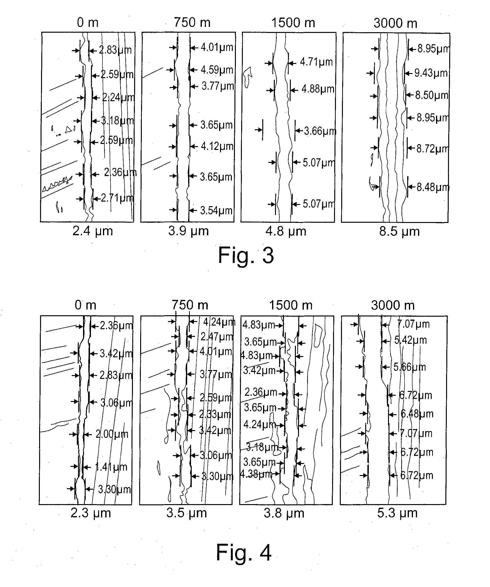
[0051]The measured edge radius was between 2 and 4 micrometres. Resharpening is therefore not necessary.

[0052]The edge radius was checked before and after coating on a scanning electron microscope (FIGS. 3 and 4).

[0053]The tool was then used on a Conturex wood milling machine from Michael Weinig AG. The milling parameters were as follows:

[0054]Speed: 12,000 U / min

[0055]Feed rate: 12,000 mm / min

[0056]The cutting edge radius was measured by means of a scanning electron microscope after 750, 1,500 and 3,000 linear me...


PUM

PropertyMeasurementUnit
wedge angleaaaaaaaaaa
thicknessaaaaaaaaaa
thicknessaaaaaaaaaa

Abstract

The invention relates to a coated woodworking tool, in particular a cutting tool comprising a tool body having a cutting part, on which cutting part a cutting edge is formed. At least the rake face or the rake and flank faces, and the cutting edge of the cutting part are coated with at least one hard-material layer and one sliding layer arranged above the at least one hard-material layer. The sliding layer may be made substantially of sulphides, tellurides or selenides having a transition metal of subgroup Va and VIa of the periodic table, in particular having Mo, Nb, Ta, W, Nb, Ta.

Description

CROSS-REFERENCE TO RELATED APPLICATIONS[0001]This application is a national phase entry under 35 U.S.C. §371 of PCT / CH2012 / 000120 filed May 25, 2012, which claims priority to Swiss Patent Application No. 911 / 11 filed May 27, 2011, the entirety of each of which is incorporated by this reference.[0002]The present invention relates to a coated woodworking tool as per claim 1 and a method for producing such coated woodworking tool as per claim 12.PRIOR ART[0003]Cutting tools are characterised by one or a plurality of wedge-shaped cutting edges arranged on a shaft or blade which are used to shape a workpiece by cutting. Depending on the nature of the cutting process, a distinction is made between machining tools for manufacturing processes involving machining and cutting tools for manufacturing processes involving cutting (see www.wikipedia.de, keyword, cutting tool).[0004]Depending on the type of material to be machined, the cutting tools used need to meet different requirements. When c...

Claims


Application Information

Patent Timeline
Patent Type & Authority Applications(United States)
IPC IPC(8): C23C28/04
CPCC23C28/044C23C14/0623C23C28/04C23C30/005C23C14/024C23C14/025C23C14/027C23C14/35
Inventor DUTTLINGER, ROLANDSCHINDLER, MAUROBLOSCH, PETER
Owner W BLOSCH
Why Eureka
Try Eureka