Hydroprocessing light cycle oil in liquid-full reactors
a technology of hydroprocessing and light cycle oil, which is applied in the treatment of hydrocarbon oils, hydrocarbon oil treatment, and treatment with plural serial cracking stages. it can solve the problems of large quantities of hydrogen, large naphtha and lighter hydrocarbons, and the inability to directly blend oil into today's diesel fuels. achieve the effect of high yield and/or quality
- Summary
- Abstract
- Description
- Claims
- Application Information
AI Technical Summary
Benefits of technology
Problems solved by technology
Method used
Image
Examples
example 1
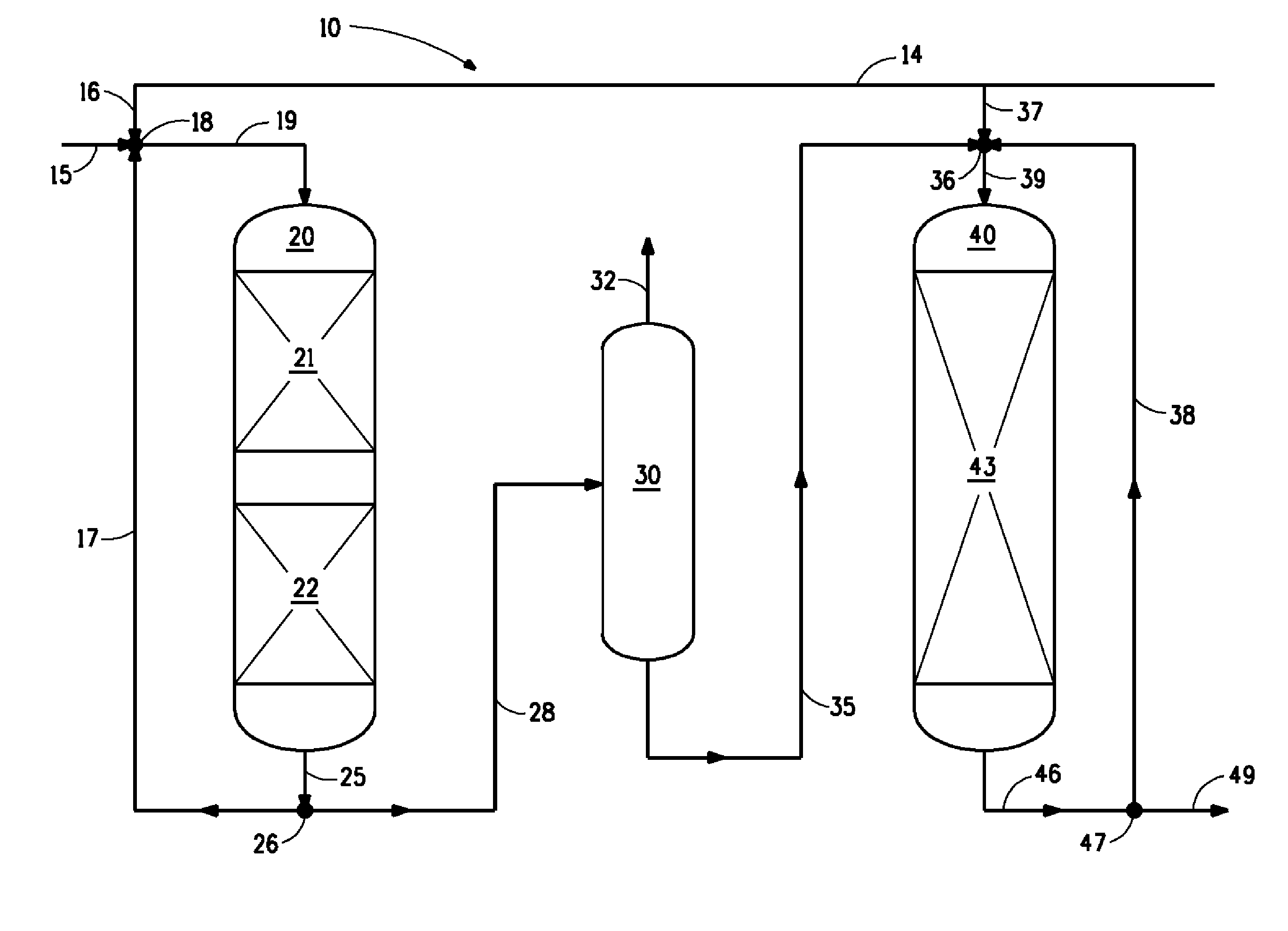
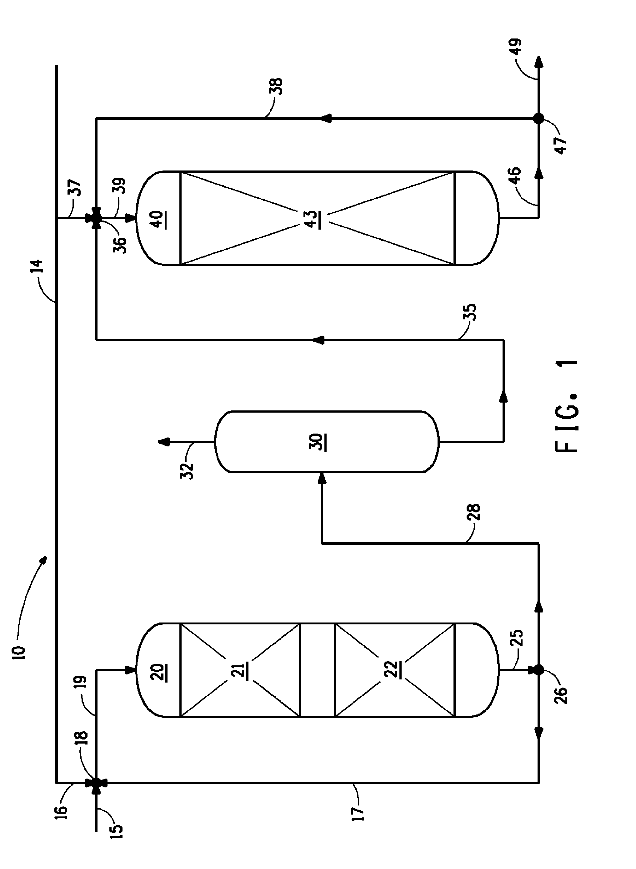
[0064]This example demonstrated the first stage of the present invention. Reactors 1-3 were equipped with a hydrotreating catalyst to accomplish hydrodenitrogenation (HDN), hydrodesulfurization (HDS) and hydrodearomatization (HDA). The catalyst, KF-860 (NiMo on γ-Al2O3 support) from Albemarle Corp., Baton Rouge, La., was in the form of extrudates of a quadralobe about 1.3 mm diameter and 10 mm long. About 22 mL, 62 mL, and 96 mL of catalyst (180 mL total) were loaded into the first, second, and third reactor, respectively. Reactor 1 was packed with layers of 30 mL (bottom) and 30 mL (top) of glass beads. Reactor 2 was packed with a layer of 10 mL (bottom) and 11 mL (top) of glass beads. Reactor 3 was packed with a layer of 7 mL (bottom) and 3 mL (top) of glass beads.
[0065]Fresh LCO feed was pumped to Reactor 1 using a reciprocating pump at a flow rate ranging from 1 mL / minute to 3 mL / minute. Total hydrogen fed to the reactors ranged between 310 N l / l to 350 N l / l (1730 scf / bbl-2180 ...
example 2
[0067]Demonstrated in this example is the second stage of the present invention wherein the stage 1 product from Example 1 is used as the feed.
[0068]Reactors 4 and 5 were filled with hydrocracking catalyst, KC2610 (NiW on a zeolite support) from Albemarle in the form of cylindrical extrudates about 1.5 mm in diameter and 10 mm long. Each reactor was filled with 60 mL of catalyst and contained a layer of 12 mL (bottom) and 24 mL (top) of glass beads. Hydrogen was injected only into the feed to reactor 4; effluent from reactor 4 flowed directly into reactor 5. The effluent from reactor 5 was split into a recycle stream and a product effluent. The liquid recycle stream flowed through a piston metering pump, to join the feed at the inlet of reactor 4.
[0069]The feed (stage 1 product from Example 1) was pumped to reactor 4 using a reciprocating pump at a flow rate of 1.5 mL / min for a LHSV of 0.75 hr−1. Hydrogen was fed at 125 N l / l (710 scf / bbl). Pressure was 13.8 MPa (138 bar). The recyc...
example 3
[0070]Demonstrated in this example is the second stage of the present invention wherein the stage 1 product from Example 1 is fractionated prior to use as the feed. The reaction conditions are otherwise similar to Example 2
[0071]A portion of the stage 1 product from example 1 was charged into 3 L batch distillation column. The column contained 5 trays, a total condenser, and reflux splitter. The column was operated under a vacuum. An electric heating mantle was used to heat the column. The column operated at a 2:1 reflux ratio. The distillation was continued until the distillate had an average density of 850 kg / m3. The bottoms from the batch distillation was used as the feed for the second stage of Example 3.
[0072]The feed (bottoms from the distillation) was pumped to reactor 4 using a reciprocating pump at a flow rate of 1.5 mL / min for a LHSV of 0.75 hr−1. Hydrogen was fed at 125 N l / l (710 scf / bbl). Pressure was 13.8 MPa (138 bar). The recycle ratio was 6. Runs were again made at ...
PUM
| Property | Measurement | Unit |
|---|---|---|
| density | aaaaa | aaaaa |
| density | aaaaa | aaaaa |
| pressure | aaaaa | aaaaa |
Abstract
Description
Claims
Application Information
 - R&D
- Intellectual Property
- Life Sciences
- Materials
- Tech Scout
- Unparalleled Data Quality
- Higher Quality Content
- 60% Fewer Hallucinations
Browse by: Latest US Patents, China's latest patents, Technical Efficacy Thesaurus, Application Domain, Technology Topic, Popular Technical Reports.
© 2025 PatSnap. All rights reserved.Legal|Privacy policy|Modern Slavery Act Transparency Statement|Sitemap|About US| Contact US: help@patsnap.com


