Organic electroluminescence light-emitting device and production method thereof

Active Publication Date: 2014-06-05
MITSUBISHI CHEM CORP
View PDF6 Cites 6 Cited by
  • Summary
  • Abstract
  • Description
  • Claims
  • Application Information

AI Technical Summary

Benefits of technology

The organic EL light-emitting device described in this patent has excellent properties of blocking external moisture, heat dissipation, and preventing deterioration of the organic electroluminescence element. This results in a longer lifespan for the device and allows for smaller weight, thickness, and recycling of the substrate. Additionally, the device can be produced more efficiently through simpler steps.

Problems solved by technology

It is known that when an organic EL light-emitting device is allowed to stand, with the organic functional layer and the cathode being exposed to the air, the device undergoes a phenomenon (shrinking) in which the non-luminescent region expands due to atmospheric moisture as if the luminescent region of the organic functional layer shrinks, resulting in a deterioration of the organic electroluminescence element.
In the case of this hollow seal, however, since the deterioration is prevented by causing the desiccant to absorb the moisture which has permeated from outside the seal, an expensive member which is made of a glass, metal, etc. and in which a recessed portion for placing the desiccant therein has been formed in the center is necessary as a sealing base.
In addition, because of the space inside the seal, the heat generated by the luminescence is less apt to be dissipated and there is a fear that the life of the organic electroluminescence element may be shortened.
Furthermore, a prolonged tact time is necessary for applying the resin used for bonding the periphery of the sealing base.
In the case of using a glass frit, an expensive apparatus such as a laser is necessary.

Method used


Image

  • Organic electroluminescence light-emitting device and production method thereof
  • Organic electroluminescence light-emitting device and production method thereof
  • Organic electroluminescence light-emitting device and production method thereof

Examples


example 1

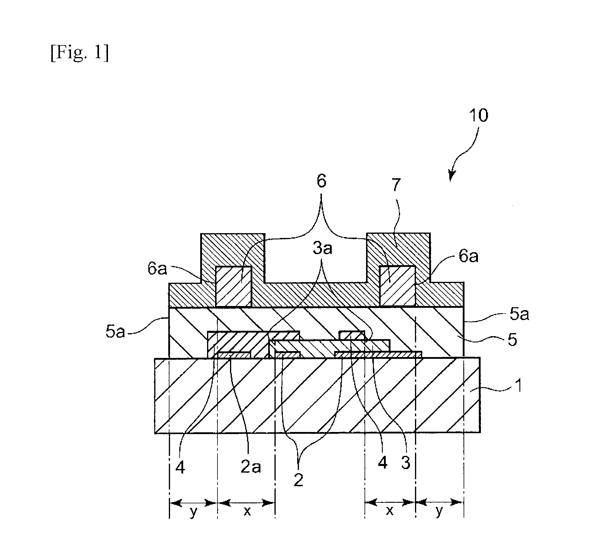
[0104]The organic EL light-emitting device shown in FIG. 1 was produced by the following method.

[0105]First, an organic electroluminescence element having a 2-mm-square luminescent region was produced in the manner shown in FIG. 3.

[0106]As an ITO substrate 1, use was made of a substrate constituted of a glass substrate 1 having a length of 3.75 cm, width of 2.5 cm, and thickness of 0.7 mm and, formed thereon, a transparent conductive film (anode 2) of indium-tin oxide (ITO) having a thickness of 70 nm.

[0107]Subsequently, a polymeric compound having the repeating structure represented by the following formula (6) (PB-1; weight-average molecular weight, 52,000; number-average molecular weight, 32,500) was mixed with 4-isopropyl-4′-methyldiphenyliodonium tetrakis(pentafluorophenyl)borate in a mass ratio of 100:20, and this mixture was dissolved in ethyl benzoate so as to result in a concentration of the mixture of 2.0% by weight, thereby preparing a composition. In the air, this compos...

example 2

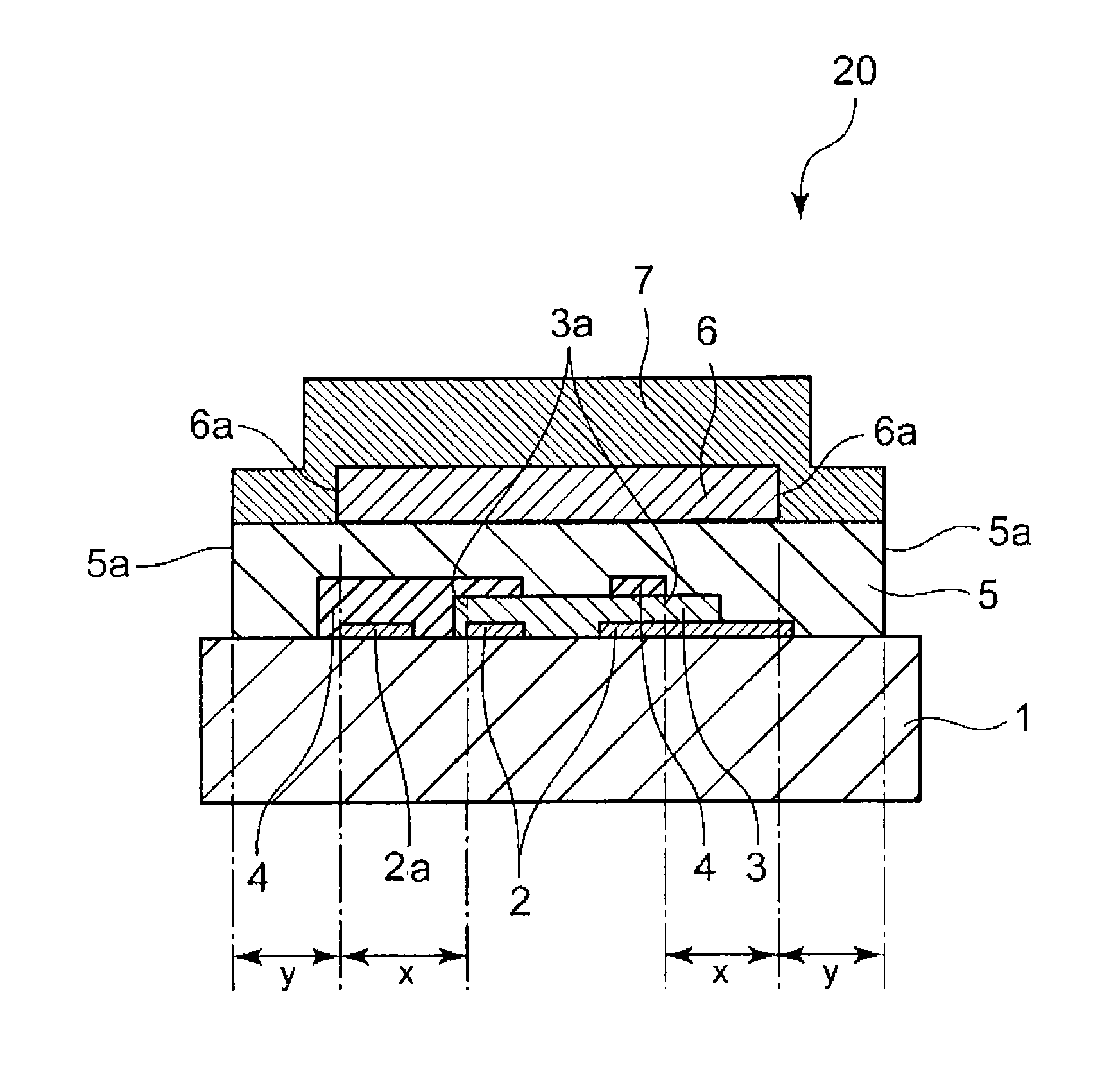
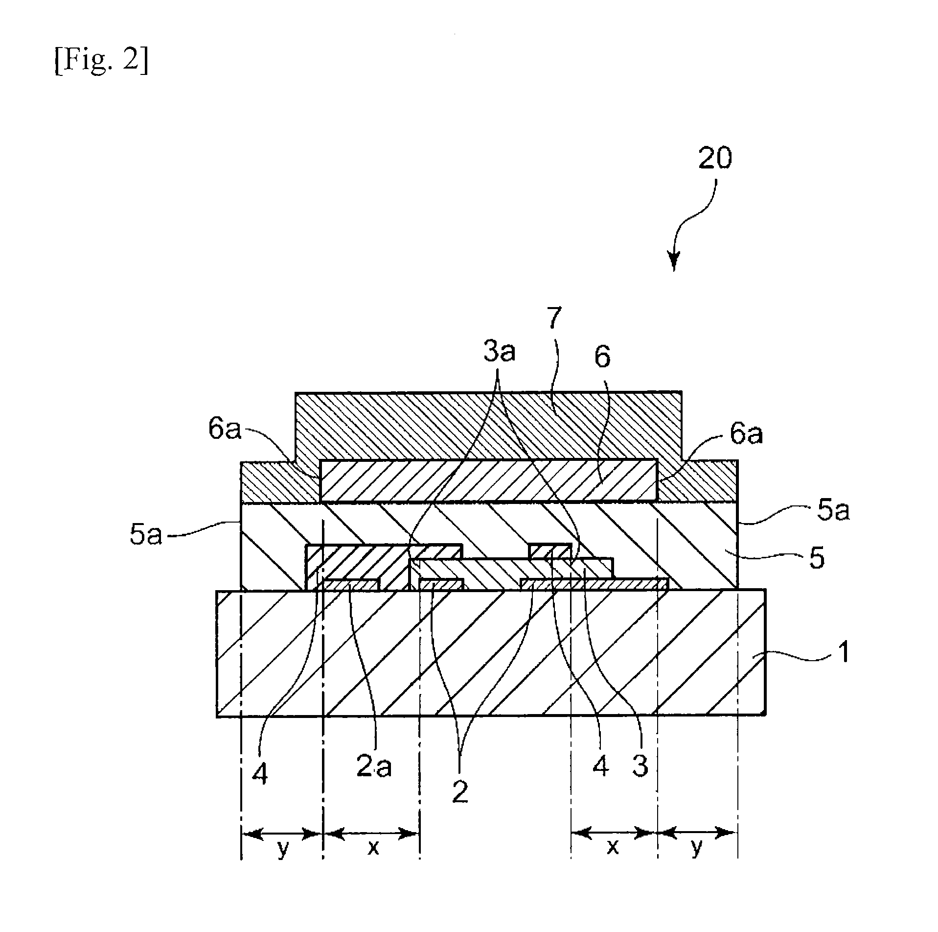
[0119]The organic EL light-emitting device shown in FIG. 2 was produced by the following method.

[0120]First, an organic electroluminescence element having a 7-mm-square luminescent region was produced in the manner shown in FIG. 3. The method for producing the organic electroluminescence element is the same as in Example 1.

[0121]Next, a backing member was produced in the manner shown in FIG. 5.

[0122]An aluminum foil having a thickness of 100 μm was cut into a 100-mm square. DryPaste-S1 (manufactured by Saes Getters), which included calcium oxide as the main component, was used as a desiccant to form a hygroscopic layer having a square shape with a thickness of 50 μm and a side length of 18 mm on the cut aluminum foil in the air by means of a screen printing machine (HP-300, manufactured by Newlong Seimitsu Kogyo Co., Ltd.). Immediately after the printing, the aluminum foil was transferred to a nitrogen atmosphere and baked on a hot plate at 200° C. for 30 minutes. This aluminum foil...

example 3

[0125]The organic EL light-emitting device shown in FIG. 2 was obtained in the same manner as in Example 2, except that in place of the 50 μm-thick sheet-form pressure-sensitive adhesive which was a thermoplastic resin NE-1 sandwiched between two PET films, use was made of a 50 μm-thick sheet-form pressure-sensitive adhesive sandwiched between two PET films and constituted of a thermoplastic resin NE-2 obtained by mixing polyisobutylene, a cyclopentadiene / dicyclopentadiene copolymer, and polybutene in a mass ratio of 23:58:19.


PUM


Abstract

An object of the present invention is to provide an organic EL light-emitting device in which a permeation and diffusion of moisture from outside are prevented and a stable light-emitting characteristic is able to be maintained for a long period. The present invention relates to an organic EL light-emitting device comprising a sealing layer, a hygroscopic layer and a protective layer, which are aligned on the back of an organic electroluminescence element under a predetermined condition, wherein the sealing layer and the protective layer are constituted from a specific material, whereby it is possible to maintain a stable light-emitting characteristic for a long period together with suppressing the deterioration caused by moisture being permeated from outside.

Description

TECHNICAL FIELD[0001]The present invention relates to an organic electroluminescence (hereinafter referred to also as “organic EL”) light-emitting device and a process for producing the device.BACKGROUND ART[0002]An organic EL light-emitting device is a device equipped with an organic electroluminescence element obtained, for example, by successively superposing a translucent substrate, such as a glass or a plastic, an anode constituted of a transparent electrode, an organic functional layer constituted of an organic thin film, and a cathode. Such organic EL light-emitting devices suitable for practical use are being developed enthusiastically in recent years for the reasons, for example, that these light-emitting devices emit light areally at high luminance with a voltage as low as several volts and that it is possible to make the devices emit light in any desired color tone by selecting luminescent substances.[0003]It is known that when an organic EL light-emitting device is allow...

Claims


Application Information

Patent Timeline
IPC IPC(8): H01L51/50H01L51/56
CPCH10K50/8423H10K50/846H10K50/8426H10K50/844H10K50/87H10K2102/351H10K50/84H10K50/00H10K71/00
Inventor SAITOU, KEIKOBANDO, YOSHIMASATAKAHASH, ATSUSHIOKAMOTO, HIDEAKI
Owner MITSUBISHI CHEM CORP
Why Eureka
Try Eureka