Device for measuring electrolyte ions using optodes and uses thereof
- Summary
- Abstract
- Description
- Claims
- Application Information
AI Technical Summary
Benefits of technology
Problems solved by technology
Method used
Image
Examples
example 1
Changes in Absorbance (Signal) at Different Potassium Ion Concentrations Using the Device for Measuring Electrolyte Ions
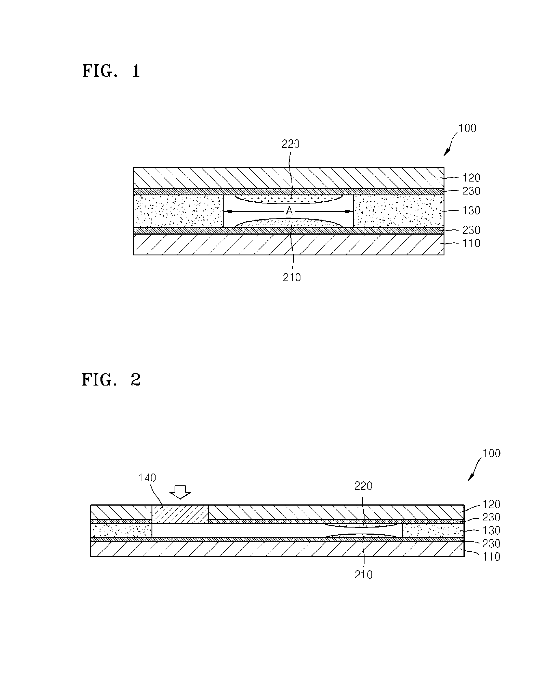
[0057]3.4 mg of potassium ionophore I (Valinomycin, Fluka), 1.2 mg of ETH 5294 that is chromoionophore (N-Octadecanoyl-Nile blue, Fluka), 1 mg of K-TpCIPB (Potassium tetrakis(4-chlorophenyl)borate, Fluka), 14 mg of polyvinyl chrloride (PVC), and 92 μL of DOS (Bis(2-ethylhexyl)sebacate, Fluka) were dissolved in 250 μL of cyclohexanone to prepare an optode mixture. The optode mixture was deposited on the first substrate of the device for measuring electrolyte ions using a drop method and then dried overnight. A solution including 0.3% of sorbitol, 3% of chaps, and 3% of PVP was added to 2-(N-morpholino)ethanesulfonic acid / N-(2-Acetamido)iminodiacetic Acid (MES / ADA) buffer having a pH of 5.5 and a concentration of 150 mM was coated onto the second substrate of the device for measuring electrolyte ions and dried overnight. The device for measuring electrolyte ions was ...
example 2
Comparing Differences in Signal Magnitude of Absorbance at Different Potassium Ion Concentrations Depending on Presence of a Buffer Coating in the Device for Measuring Electrolyte Ions
[0059]A mixture having an identical composition to the optode mixture used in Example 1 was prepared and coated on the first substrate with a potassium optode. Two devices for measuring electrolyte ions were then manufactured, one device for measuring electrolyte ions coated with a buffer of 550 mM bis-tris HCl, 0.1% of sorbitol, 0.7% of chaps, and 4% of PVP, and the other device for measuring electrolyte ions without the buffer. By adding potassium ions having a uniform concentration to a serum separation tube (SST) blood sample, differences in the signal magnitudes of absorbance at different potassium concentrations at a wavelength of 630 nm were compared. FIG. 11 shows a difference in the signal magnitudes of absorbance measured according to a potassium concentration in a sample using the device for...
example 3
Reduced Efficiency of Optode Due to Leaching of Optode Components
[0060]A device for measuring electrolyte ions was manufactured to be identical to the device for measuring electrolyte ions of Example 1. Absorbance at different potassium ion concentrations was measured according to different amounts of time passed after coating the optode. FIG. 12 shows a result of measuring absorbance at different concentrations of potassium ions in a device for measuring electrolyte ions according to passage of time. As shown in FIG. 12, as time passed after coating of the optode, signal magnitude of the absorbance at different potassium ion concentrations decreased. This is because, as time passed after the coating, parts of the optode components leach out to the surroundings.
PUM
 Abstract
Description
Claims
Application Information
 - R&D
- Intellectual Property
- Life Sciences
- Materials
- Tech Scout
- Unparalleled Data Quality
- Higher Quality Content
- 60% Fewer Hallucinations
Browse by: Latest US Patents, China's latest patents, Technical Efficacy Thesaurus, Application Domain, Technology Topic, Popular Technical Reports.
© 2025 PatSnap. All rights reserved.Legal|Privacy policy|Modern Slavery Act Transparency Statement|Sitemap|About US| Contact US: help@patsnap.com


