Process for producing oxygen reducing catalyst and uses thereof

a technology of oxygen reducing catalyst and oxygen reducing ability, which is applied in the direction of physical/chemical process catalyst, electrochemical generator, cell component, etc., can solve the problems of insufficient oxygen reducing ability, unsatisfactory practical use performance, and high cost of noble metals, and achieve the effect of sufficient oxygen reducing ability in practical us

Inactive Publication Date: 2014-06-26
SHOWA DENKO KK
View PDF6 Cites 7 Cited by
  • Summary
  • Abstract
  • Description
  • Claims
  • Application Information

AI Technical Summary

Benefits of technology

[0047]The process for producing an oxygen reducing catalyst of the present invention can provide an oxygen reducing cat...

Problems solved by technology

However, since these noble metals are expensive and limited in resource amount, development of alternative catalysts has been desired.
Conventional catalysts alternative to noble metals includ...

Method used


Image

  • Process for producing oxygen reducing catalyst and uses thereof
  • Process for producing oxygen reducing catalyst and uses thereof

Examples


example 1

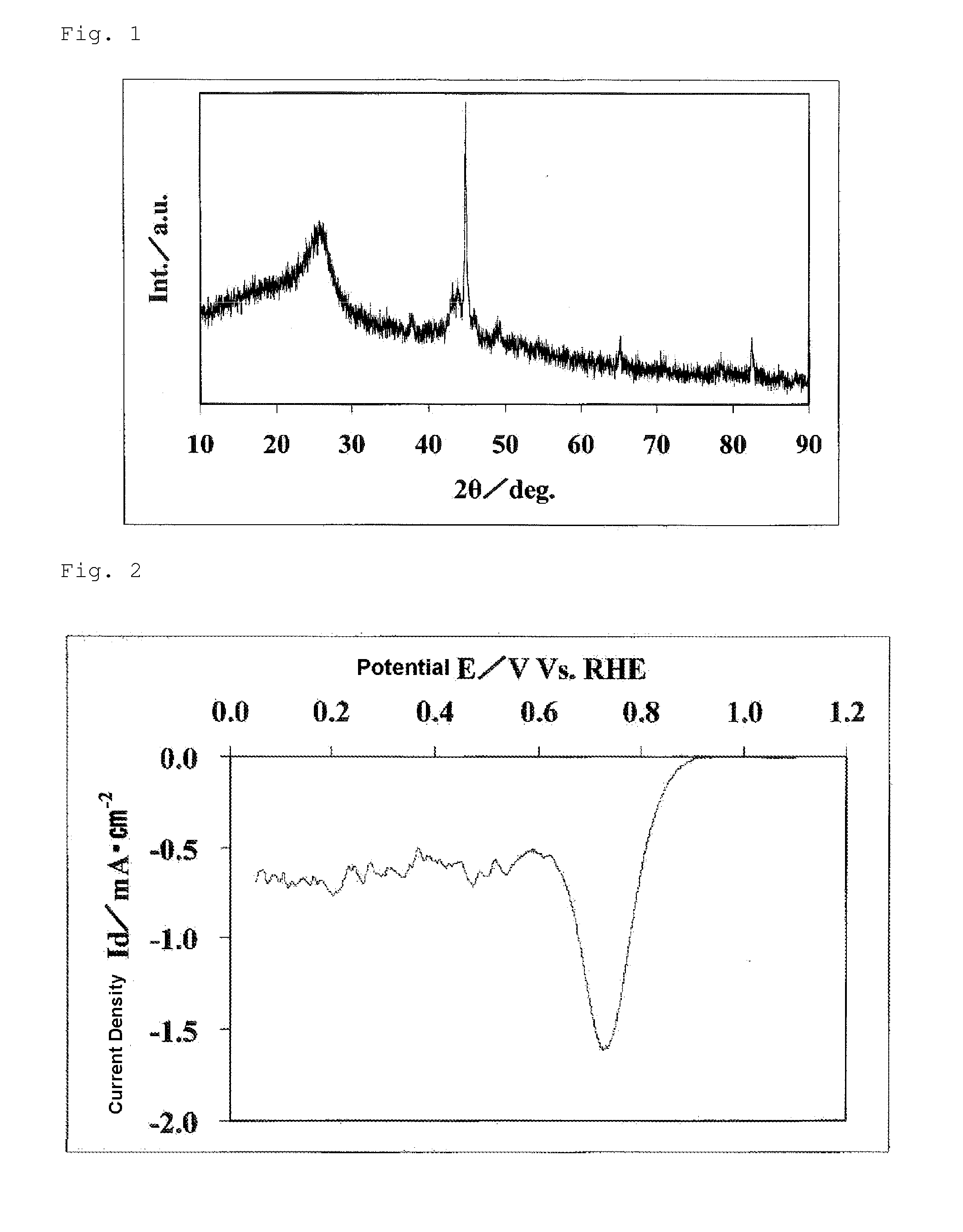
[0160]10.043 g of glycine and 0.582 g of iron acetate were weighed and dissolved in 120 ml of water to obtain an aqueous solution. To 5.118 ml of acetylacetone, 32 ml of acetic acid was added to obtain a mixed liquid. The mixed liquid was added to the aqueous solution, and these were sufficiently stirred. The resultant solution had pH of 3.3. The resultant solution was treated at 60° C. on a water bath with an evaporator, to be dried. The resultant solid substance was crushed with a mortar. This crushed product was introduced to a quartz tubular furnace. The furnace was filled with a mixed gas atmosphere of a hydrogen gas and a nitrogen gas containing 4 vol % of a hydrogen gas. The temperature in the furnace was increased to 900° C. at a heating rate of 20° C. / min, and was retained for 60 minutes, whereby the crushed product was heat-treated. Thereafter, the product was allowed to cool, and an iron oxycarbonitride was obtained. The resultant iron oxycarbonitride was crushed with a m...

example 2

[0165]By the same operation as in Example 1 except that 10.043 g of glycine was replaced by 11.919 g of alanine, a sample powder (hereinafter referred to as the “catalyst (2)”.) was obtained. The catalyst precursor solution had pH of 3.2.

[0166]The result of the elemental analysis of the catalyst (2) is shown in Table 1. The proportion of the atomic number of iron, the atomic number of carbon, the atomic number of nitrogen and the atomic number of oxygen is represented by iron:carbon:nitrogen:oxygen=1:x:y:z. The values x, y and z are shown in Table 1.

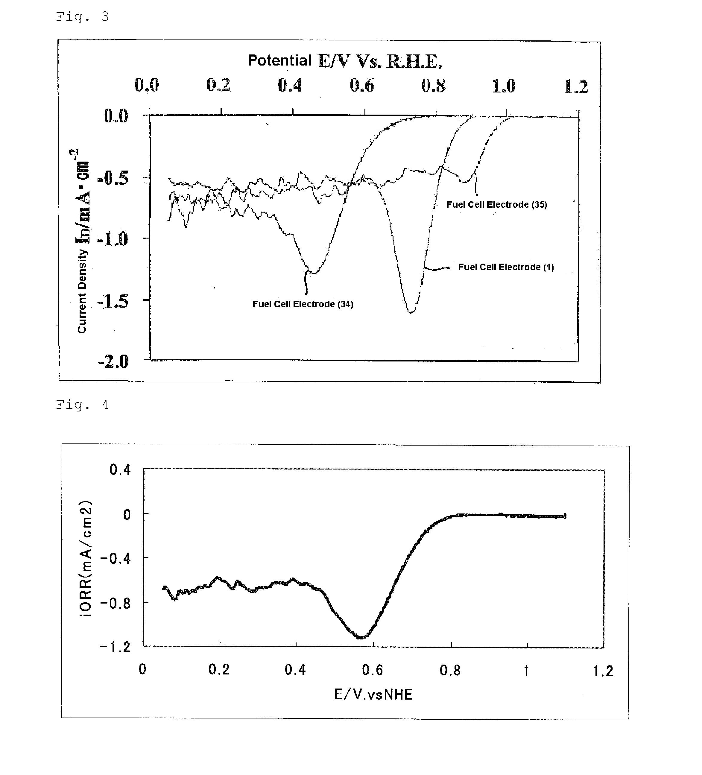
[0167]Regarding the catalyst (2), the oxygen reduction current density obtained in the evaluation of the oxygen reducing ability and the BET specific surface area are shown in Table 1. From this oxygen reduction current density, the catalyst (2) was found to have high catalytic performance. The electrode used in this evaluation was defined as a fuel cell electrode (2).

example 3

[0168]By the same operation as in Example 1 except that 10.043 g of glycine was replaced by 8.838 g of glycylglycine, a sample powder (hereinafter referred to as the “catalyst (3)”.) was obtained. The catalyst precursor solution had pH of 3.3.

[0169]Regarding the catalyst (3), the oxygen reduction current density obtained in the evaluation of the oxygen reducing ability and the BET specific surface area are shown in Table 1. From this oxygen reduction current density, the catalyst (3) was found to have high catalytic performance. The electrode used in this evaluation was defined as a fuel cell electrode (3).


PUM

PropertyMeasurementUnit
Temperatureaaaaaaaaaa
Percent by massaaaaaaaaaa
Cooling rateaaaaaaaaaa

Abstract

A process for producing an oxygen reducing catalyst including a step of heat-treating, in a non-oxidizing atmosphere, a catalyst precursor including a compound (i) supplying a carbon element and a nitrogen element by heating in a non-oxidizing atmosphere, and a compound (ii) containing at least one element of iron and cobalt. Also disclosed is an oxygen reducing catalyst, a fuel cell catalyst layer including the oxygen reducing catalyst, an electrode including the fuel cell catalyst layer, a membrane-electrode assembly including the electrode and a fuel cell including the membrane-electrode assembly.

Description

TECHNICAL FIELD[0001]The present invention relates to a process for producing an oxygen reducing catalyst and uses thereof. In more detail, the present invention relates to a process for producing an oxygen reducing catalyst comprising at least one of iron and cobalt as a metal that has catalytic performance sufficient in practical uses.BACKGROUND ART[0002]A polymer electrolyte fuel cell is a fuel cell in which a polymer solid electrolyte is sandwiched between an anode and a cathode, a fuel is supplied to the anode, and oxygen or air is supplied to the cathode, whereby oxygen is reduced at the cathode to produce electricity. As the fuel, hydrogen, methanol, or the like is mainly used.[0003]To enhance a reaction rate in a fuel cell and to enhance the energy conversion efficiency of the fuel cell, a layer containing a catalyst (hereinafter also referred to as a “fuel cell catalyst layer”) has been conventionally disposed on the surface of a cathode (air electrode) or the surface of an...

Claims


Application Information

Patent Timeline
IPC IPC(8): H01M4/90H01M8/10
CPCH01M4/9041H01M8/1007Y02E60/50H01M4/9091
Inventor ICHIOKA, KAZUNORIIMAI, TAKUYAYU, CHUNFU
Owner SHOWA DENKO KK
Why Eureka
Try Eureka