High voltage transmission line cable based on textile composite material

a technology of textile composite materials and transmission lines, applied in the direction of power cables, cables, insulated conductors, etc., can solve the problems of difficult to separate fullerenes from other products, difficult to use gaseous hydrocarbon atmosphere as an industrial production method, and inability to meet the requirements of high-voltage transmission lines

Active Publication Date: 2014-07-03
SIMENHAUS ZIDKIYAHU +1
View PDF6 Cites 18 Cited by
  • Summary
  • Abstract
  • Description
  • Claims
  • Application Information

AI Technical Summary

Problems solved by technology

As a general rule, carbon deposited after thermal decomposition is in particulate form, use of gaseous hydrocarbon atmosphere requires considerable care, and is frequently considered to be impractical as an industrial production method.
It should be noted that, practically, it is difficult to separate fullerenes from other products.
A disadvantage of this method derives from the impossibility to produce a current-conducting Element (CCE) having a preset electrical resistance value and, the resulting CCE has a low tensile strength and a low breaking point.
The carbon coating layer, applied onto the cable body in order to create a CCE is uneven and coarse resulting in “upper current” generation that breaks down the cable's cover.
It is also impossible to produce a CCE having a preset electrical resistance value and a high breaking strength point.
This method is very complicated technologically and it does not allow producing a CCE with a preset electrical resistance value.
Moreover, the use of a gaseous hydrocarbon atmosphere requires considerable care, and is frequently considered to be impractical as an industrial method.
However, a disadvantage of this method derives from the fact that the element possesses insufficient flexing and has a low tensile strength.
These features sharply decrease manufacturability and aggravate the production process.
As mentioned above, the products according to WO 01 / 47825 A1 possess inadequate tensile strength and insufficient flexibility that cause the cable to fracture very often during the process of drawing on the cable, which is done by applying force to an end of the cable.
We hardly ever managed to produce such CCEs of 100 meter length.
It is obvious that the abovementioned CCEs lack sufficient tensile strength.
Furthermore, upon occurrence of such fractures one is forced to stop the manufacturing process to clean the furnace and insert a new quartz rope and to restart the carbon coating process.
Moreover, because of its insufficient (low) tensile strength, if it is required to coat the rope with any metal, the impregnation of a metal-cover over it could be hardly done, even when the cable is drawn at a low speed, and because of cable fracture it will be imperative to clean the impregnating appliance, to insert a new CCE and to start the coating process again.
As a result of the abovementioned malfunction, elements manufactured according to the methods disclosed in WO 01 / 47825 are ineffective even useless for large production batches.
Moreover, the CCEs or the cables produced as described in WO 01 / 47825 do not provide sufficient protection against noise.
Consequently, computers and radio communication are frequently disturbed.

Method used


Image

  • High voltage transmission line cable based on textile composite material
  • High voltage transmission line cable based on textile composite material
  • High voltage transmission line cable based on textile composite material

Examples


example no.1

Example No. 1

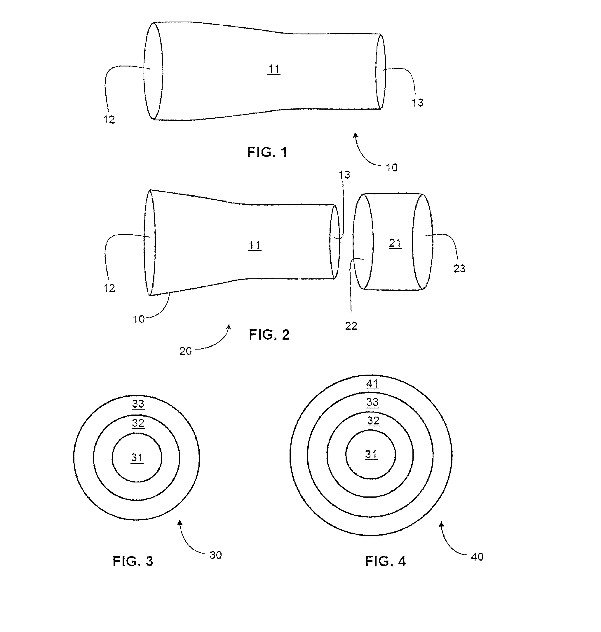
[0140]A Kevlar rope, at a target diameter of 1.0 mm, made of 8 Kevlar yarns of 58.8 tex, having a tensile strength of at least 200 cN / tex each, was produced on a ShP-12-4 machine and was used as a core for braiding over it a sleeve-coat. The Quartz coat, made of quartz yarns of 17×4×1 (68 tex) was produced on a ShP-12-4 braiding machine.

[0141]The obtained Kevlar-quartz substrate of 1.5 mm was drawn at a velocity of 1.0 m / sec, through a basin, which contained a peat solution extracted in xylol, at a concentration of 3% w / w hydrocarbons per xylol. The immersed substrate was conveyed, via a tube alloy, situated in the mid-axis of the pyrolysis chamber, heated at 650° C., pulled manually at same velocity. The total added weight of the carbon mass over the core was predetermined at 10% w / w.

example no.2

Example No. 2

[0142]A CCE made according to Example 1 above was coated with an additional carbon layer by drawing it at a velocity of 5.0 m / sec through a furnace heated at 1100° C., which contained a pyrolysis camber with an immersion basin, that contained a peat composite solution of carbon and hydro-carbonyls metal at a concentration ratio of 20:1, extracted in xylol, so its relative concentration of hydrocarbons per xylol was of 6% w / w. The immersed CCE was conveyed, via a properly adjusted tube alloy, which was situated in the mid-axis of the pyrolysis chamber.

[0143]The obtained CCE, with the double carbon layers, was pulled out by a winding machine at the same velocity. The final total added carbon mass weight was 15% w / w.

example no.3

Example No. 3

[0144]CCEs that were prepared according to Examples 1 and 2 were exposed to a blowing process in a “Boulat” unit, heated at a 900° C., and were coated with platinum metal. The resulted catalyst was tested on VAZ-2106 car (A-76 petrol) by using a AFA-121 (focused at CO) and UG-2 (focused at carbon and hydrogen). Tests results indicated that the neutralization rate was 95% at 200° C.


PUM

PropertyMeasurementUnit
diameteraaaaaaaaaa
diameteraaaaaaaaaa
melting pointaaaaaaaaaa

Abstract

An electric transmission cable having a current conductive element comprising a braided core formed of a plurality of high modulus synthetic armored yarns, each yarn being of at least 53.6 tex and having a tensile strength of at least 200 cN / tex (centiNewton / tex), and the core being of a diameter in the range of 0.7 mm to 4.5 mm and being surrounded by a quartz sleeve covered on an outer surface thereof by a carbon layer.

Description

RELATED APPLICATIONS[0001]This application claims priority to Israeli Patent Application Serial No. IL 223937 filed Dec. 27, 2012, which is incorporated herein by reference.BACKGROUND OF THE INVENTION[0002]1. Field of the Invention[0003]The invention relates to high voltage cables having current-conductive-elements (CCE) made of a textile composite material, coated with nano-carbonaceous particles.[0004]2. Background and Related Art[0005]A variety of ways to coat surfaces of non-metallic substances (e.g., glass, ceramics, quartz, etc.) with a carbon compound layer are well known in the art.[0006]U.S. Pat. No. 2,556,616 for example, teaches a method to deposit a carbon coating by thermally decomposing an organic material to form carbon as a solid decomposition product, where such decomposing is usually effected within a porous body, after the body has been impregnated with a suitable organic material. This technique is often used as the basis for manufacturing solid body carbon resis...

Claims


Application Information

Patent Timeline
Patent Type & Authority Applications(United States)
IPC IPC(8): H01B7/29
CPCH01B7/29H01B3/50H01B7/292H01B1/18H01B5/105H01B7/1825H01B3/08D07B1/147D07B1/162
Inventor SIMENHAUS, ZIDKIYAHUFILATOV, VLADIMIR N.
Owner SIMENHAUS ZIDKIYAHU
Why Eureka
Try Eureka