Sensor element, dew condensation sensor, humidity sensor, method for detecting dew condensation, and dew-point measurement device

a technology of dew condensation and sensor element, which is applied in the direction of instruments, porous material analysis, and investigation of moving fluid/granular solids, etc., can solve the problems of inability to predict the occurrence of dew condensation in time, the dew point meter cannot sense the occurrence of dew condensation in advance, and the dew point is easy to be confused with the dew point, etc., to achieve the effect of short time, good precision and simple operation

Inactive Publication Date: 2014-07-03
NIPPON STEEL CHEMICAL CO LTD
View PDF1 Cites 46 Cited by
  • Summary
  • Abstract
  • Description
  • Claims
  • Application Information

AI Technical Summary

Benefits of technology

[0029]With the sensor element of the invention, various sensing may be performed more simply in a short time with good precision, due to the use of the metal fine-particle dispersed composite that includes a matrix having a 3D network structure including a solid framework and voids defined by the solid framework, and metal fine-particles dispersed three-dimensionally in this matrix.

Problems solved by technology

In processes of manufacturing and utilizing the electronic devices, moisture that causes a short circuit in electronic components such as an electronic circuit has become a big problem, and thus there is demand to develop a method of sensing dew condensation in advance.
However, since the electrostatic capacity-type dew point meter measures a dew point indirectly from a measurement result of the capacitance of the high molecular compound or aluminum oxide, it must have a problem that an error easily occurs in the dew point.
In addition, although a mirror-cooling dew point meter obtains a more accurate dew point than the electrostatic capacity-type dew point meter, since the dew point temperature is measured once dew condensation occurs on a mirror surface, the mirror-cooling dew point meter can't sense occurrence of dew condensation in advance.
Accordingly, a certain period of time is required for predicting dew condensation, such that there was a problem that the occurrence of dew condensation cannot be predicted immediately.
As mentioned above, the prior art for predicting dew condensation required a mechanism for always maintaining the dew condensation sensor at a temperature lower than the ambient temperature, and had a problem that the detection of dew condensation takes time.

Method used


Image

  • Sensor element, dew condensation sensor, humidity sensor, method for detecting dew condensation, and dew-point measurement device
  • Sensor element, dew condensation sensor, humidity sensor, method for detecting dew condensation, and dew-point measurement device
  • Sensor element, dew condensation sensor, humidity sensor, method for detecting dew condensation, and dew-point measurement device

Examples


first embodiment

Dew Condensation Sensor

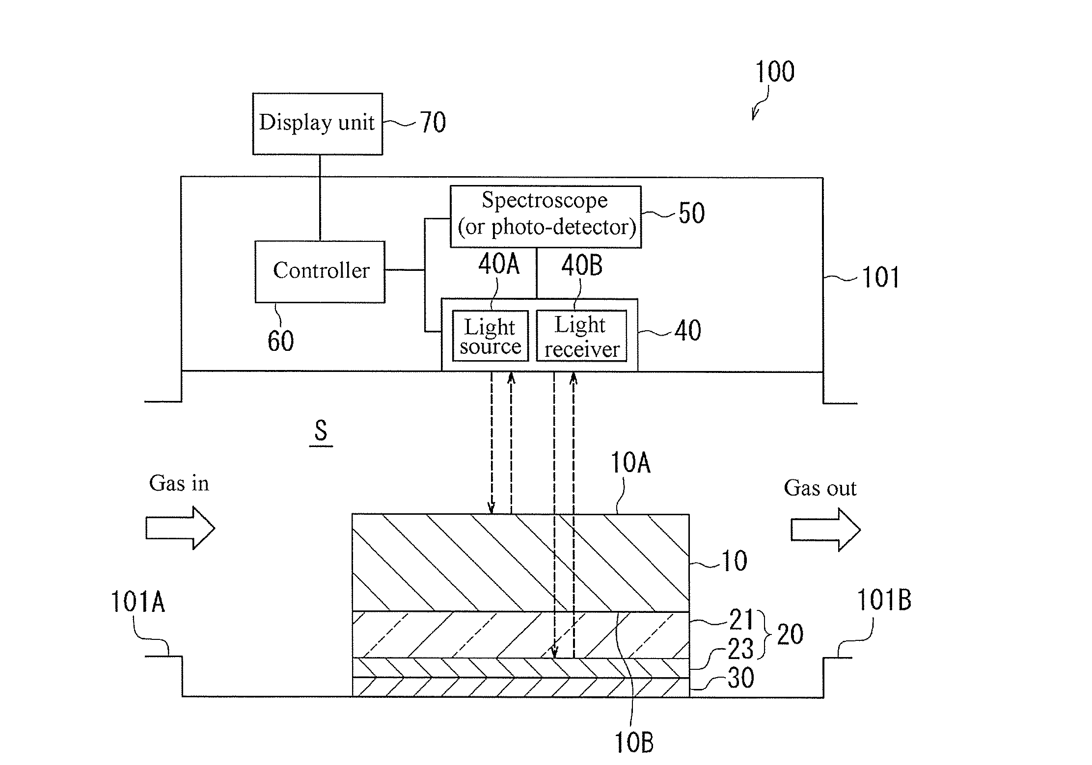
[0128]Next, a dew condensation sensor according to the first embodiment of the sensor element of the invention is described with reference to FIGS. 5 to 9. FIG. 5 illustrates a schematic configuration of a dew condensation sensor 100 according to an embodiment of the invention. The dew condensation sensor 100 includes a nano-composite 10, a light reflective member 20 disposed on one side of the nano-composite 10, a protection layer 30 laminated on the light reflective member 20, a light source / light receiver 40 disposed facing the nano-composite 10, a spectroscope (or photo-detector) 50 detecting light reflected by the light source / light receiver 40, a controller 60 connected to the light source / light receiver 40 and the spectroscope (or photo-detector) 50 and used for overall control thereof, and a display unit 70 connected to the controller 60. In the dew condensation sensor 100, the nano-composite 10, the light reflective member 20 and the protection layer ...

example 1

Fabrication of Nano-Composite

[0176]To 6 g of a boehmite powder (trade name: C-01, produced by Taimei Chemicals Co., Ltd, with a mean particle diameter of 0.1 μm and a cubic particle shape), 17 g of water and 0.5 g of acetic acid were added, and a 5-min ultrasonic treatment was performed. Further, 17 g of ethanol, 0.6 g of 3-aminopropyltriethoxysilane and 1.25 g of chloroauric acid tetrahydrate were added, followed by a 5-min ultrasonic treatment, thereby preparing a gold complex-containing slurry 1. The proportion of Au in the gold complex-containing slurry 1 at this moment was 10 weight parts relative to 100 weight parts of boehmite. Next, the resulting gold complex-containing slurry 1 was coated on a glass face of a substrate (12 cm square) having a three-layer structure of Ni—Cr alloy film of 193 nm thick / Ag film of 233 nm thick / glass substrate of 0.7 mm thick using a spin coater (trade name: Spincoater 1H-DX2, made by Mikasa Co., Ltd.), dried at 70° C. for 3 minutes and at 130° ...

example 2

[0184]Except that the cooling speed was set to 1.0° C. / min, the cooling properties were evaluated in the same manner as in Example 1. The standard deviation G of the absorption peak wavelength from 25° C. to 15° C. was 0.113 nm, and the mean value ν of the absorption peak wavelength was 569.794 nm. When the temperature of the surface of the nano-composite 1 reached 10.6° C., the absorption peak wavelength was shifted to the longer-wavelength side in excess of σ±3σ. In addition, as the surface temperature of the nano-composite 1 reached 8.6° C., the absorption peak wavelength and reflected-light intensity at the wavelength of 700 nm rapidly varied with 8.6° C. as the inflection point. From the above, it was confirmed that the nano-composite 1 is capable of detecting dew condensation at a temperature higher than the dew point (4.50±0.07° C.) measured using the minor-cooling dew point meter.


PUM

PropertyMeasurementUnit
particle diametersaaaaaaaaaa
volume fractionaaaaaaaaaa

Abstract

A dew condensation sensor is described, including a nano-composite for generating local surface plasmon resonance, a light reflecting member disposed on one side of the nano-composite, a protection layer laminated on the light reflecting member, a light source/light receiver disposed facing the nano-composite, a spectroscope (or photo-detector) for detecting the light reflected by the light source/light receiver, a controller connected to the light source/light receiver and the spectroscope (or photo-detector) and used for overall control thereof, and a display unit connected to the controller. The dew condensation sensor detects occurrence of dew condensation based on the variation in the absorption spectrum, the absorption intensity or the reflected-light intensity of the local surface plasmon resonance of the nano-composite.

Description

TECHNICAL FIELD[0001]The invention relates to a sensor element useful in various types of sensing, and a dew condensation sensor, a humidity sensor, a dew condensation detecting method and a dew point measurement device as application examples of the sensor element.BACKGROUND ART[0002]Nano-sized fine-particles have a geometrically high specific surface area, and also exhibit changes in optical properties, lowering of melting point, high catalytic properties, high magnetic properties and so on due to quantum size effects. Hence, the fine-particles are expected to offer new functions which could not be achieved with bulk materials, such as improvement of catalytic reaction, luminescence properties and other chemical or physical conversion properties, and have been a very important material in various fields such as electronic material, catalyst material, phosphor material, luminous body material, medical supplies and so on. In particular, for metal fine-particles with a size of about ...

Claims


Application Information

Patent Timeline
Patent Type & Authority Applications(United States)
IPC IPC(8): G01N21/65G01N21/47G01N27/414
CPCG01N21/658B82Y15/00Y10S977/92G01N27/4146Y10S977/773G01N21/47G01N21/554G01N21/3554G01N21/55
Inventor SHINTA, RYUZOMATSUMURA, YASUFUMIENOMOTO, YASUSHI
Owner NIPPON STEEL CHEMICAL CO LTD
Why Eureka
Try Eureka