Dry sorbent injection (DSI) recovery system and method thereof

a dry sorbent injection and recovery system technology, applied in the direction of bicarbonate preparation, solid waste management, liquid gas reaction process, etc., can solve the problems of high operational cost of dsi systems, reduce operational cost, reduce the concentration of sodium, and reduce the ph of post dry sorbent injection fly ash

Inactive Publication Date: 2014-07-24
NEUMANN SYST GROUP
View PDF8 Cites 10 Cited by
  • Summary
  • Abstract
  • Description
  • Claims
  • Application Information

AI Technical Summary

Benefits of technology

[0009]An advantage of the invention is to provide recovered sorbent for reducing operational cost of a dry sorbent injection process.
[0010]Still yet another advantage of the invention is to reduce the concentration of sodium in post dry sorbent injection fly ash.
[0011]Still another advantage of the invention is to reduce the pH of post dry sorbent injection fly ash.
[0012]Yet still another advantage of the invention is to reduce the leachability of heavy metals in post dry sorbent injection fly ash.
[0013]Additional features and advantages of the invention will be set forth in the description which follows, and in part will be apparent from the description, or may be learned by practice of the invention. The objectives and other advantages of the invention will be realized and attained by the structure particularly pointed out in the written description and claims hereof as well as the appended drawings.
[0014]An embodiment of the invention relates to system and method for recovering sodium bicarbonate from a solid waste, and more particularly to a method and system for recovering sodium bicarbonate from fly ash of a coal fired plant collected downstream of an injection process for pollution reduction from the combustion process.

Problems solved by technology

DSI systems suffer from high operational expenses due to high cost of the sodium sorbents and excessive chemical usage in the case of SO2 control.
Additionally, the high sodium concentration present in post-DSI fly ash has been shown to increase the leachability of metals from the fly ash, increasing concerns regarding the disposal of post-DSI fly ash.

Method used


Image

  • Dry sorbent injection (DSI) recovery system and method thereof
  • Dry sorbent injection (DSI) recovery system and method thereof
  • Dry sorbent injection (DSI) recovery system and method thereof

Examples


examples

[0112]Without intending to limit the scope of the invention, the following examples illustrate how various embodiments of the invention may be performed, made and / or used.

[0113]A normalized stoichiometric ratio (NSR, mole of Na2 injected / mole of SO2 in the gas inlet) for trona of 3.2 was assumed, which corresponds to about a 90 percent (%) removal of SO2 in a power plant utilizing a baghouse for particulate matter control. This usage indicates that a large amount of the reactive portion of trona remains unused, and will be found in the fly ash as sodium carbonate due to calcination of the trona in the DSI process. The approximate composition of fly ash collected downstream of a DSI system operating at an NSR of 3.2 when low sulfur coal is burned were calculated by mass balance and are given below in Table 1. This estimated post-DSI fly ash composition was used as the basis for the Examples reported herein.

TABLE 1Estimated Fly Ash CompositionApproximateComponentweight %Fly ash57Na2CO...

examples 1-5

[0115]Examples 1-5 detailed herein serve as proof of concept experiments to demonstrate the reaction between sodium carbonate and lime found in post-DSI fly ash. It is expected that reaction yields will increase with additional process optimization as known in the art.

[0116]Step 1:

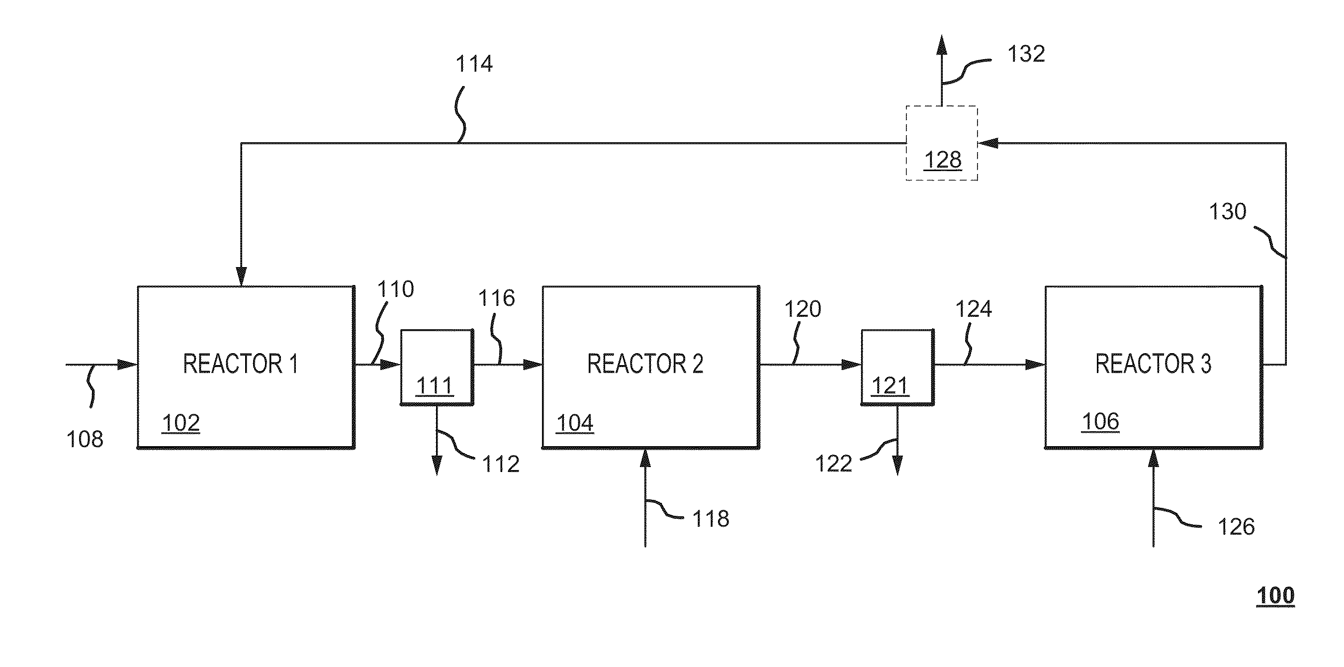
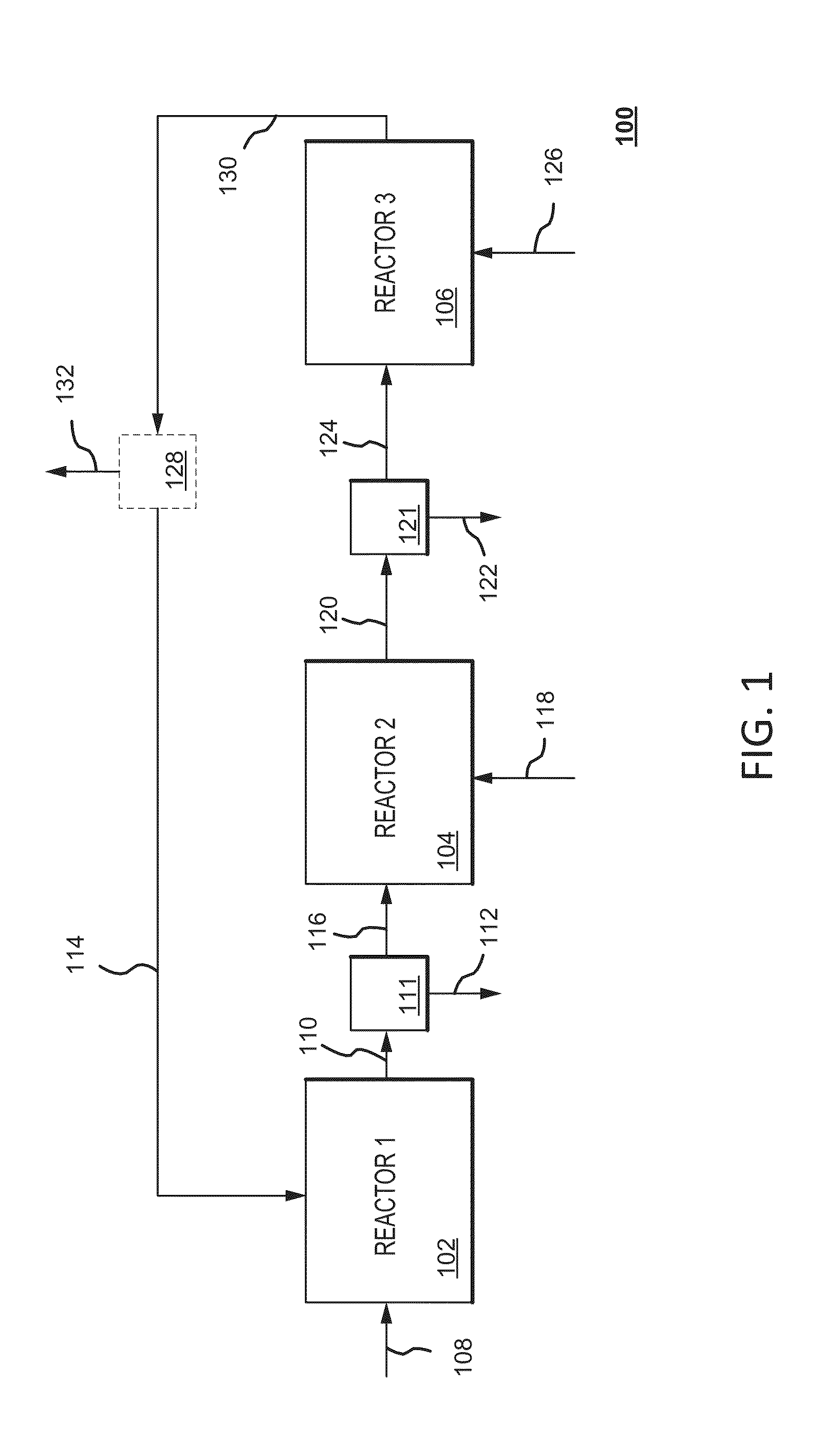
[0117](Formation of sodium hydroxide) This Step involves the formation of sodium hydroxide from the reaction between Na2CO3 and Ca(OH)2 according to Equation 1 herein.

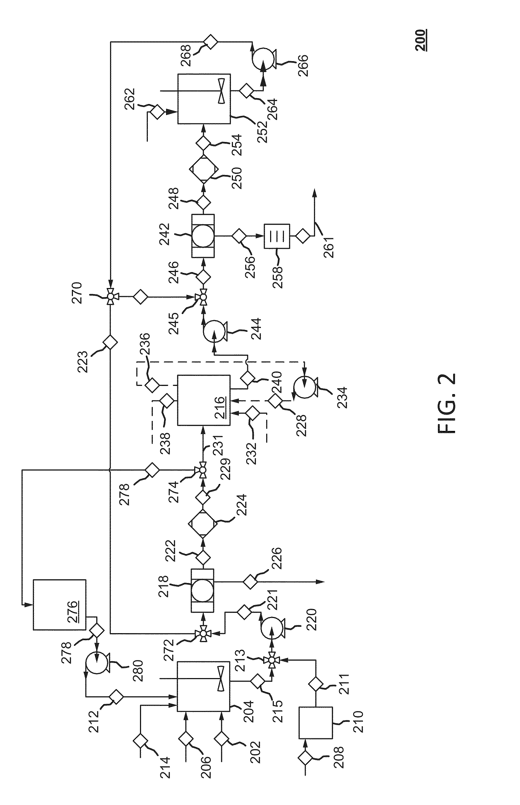
[0118]In Examples 1 to 5, the setup included a stirred 4 liter beaker. Reactants shown in Table 2 were added to the beaker in the quantities specified in the Table 2. These were stirred at ambient temperature and pressure for an hour and then filtered through a vacuum filtration apparatus.

[0119]Next, the pH of the filtrate was measured and the hydroxide concentration was determined by titration. The solids included fly ash and CaCO3, these solids precipitated from the reaction between Na2CO3 and Ca(OH)2 according to Equation 1. The solids wer...

examples 6-10

[0121]Examples 6 to 10 detailed here served as characterization experiments for product yield and purity as a function of NaCl concentration.

[0122]Step 2:

[0123](Synthesis of sodium bicarbonate) Step 2 involves the synthesis of sodium bicarbonate from CO2 and the sodium hydroxide generated in Step 1 as well as the residual, un-reacted sodium carbonate from Step 1 as per Equations 2 and 3 herein. NaCl is added to the solution in order to promote the precipitation of NaHCO3 but it is not consumed in the reaction.

[0124]The laboratory apparatus for Step 2 includes a flask with a fitted disk sitting on the bottom which is configured for CO2(g) flow. The filtrate from Step 1 is placed in the flask and nominally about 15 percent (%) NaCl by weight is added. When the NaCl is dissolved, CO2 (g) is bubbled through the solution at ambient temperature for a minimum of 40 minutes up to 1 hour. A white precipitate forms. The mixture is filtered through a vacuum filtration apparatus and the solid i...


PUM

PropertyMeasurementUnit
particle sizeaaaaaaaaaa
pHaaaaaaaaaa
particle sizeaaaaaaaaaa

Abstract

The invention generally relates to system and method for recovering sodium bicarbonate from a solid waste, and more particularly to a method and system for recovering sodium bicarbonate from fly ash of a coal fired plant collected downstream of an injection process for pollution reduction from the industrial process.

Description

[0001]This application claims the benefit of U.S. Provisional Patent Application No. 61 / 754,477 filed on Jan. 18, 2013, which is fully incorporated herein by reference as if fully set forth herein.BACKGROUND OF THE INVENTION[0002]1. Field of the Invention[0003]The present invention generally relates to system and method for recovering sodium bicarbonate from a solid waste, and more particularly to a method and system for recovering sodium bicarbonate from fly ash of a coal fired plant collected downstream of an injection process for pollution reduction from the combustion process.[0004]2. Discussion of the Related Art[0005]Dry sorbent injection (DSI) using sodium-based sorbents is an accepted technology for controlling SO2 and other acid gas emissions in post-combustion flue gases such as those emitted by pulverized coal burning power plants. The dry sorbent, typically either trona or sodium bicarbonate, is injected into the flue gas upstream of the particulate control device, e.g.,...

Claims


Application Information

Patent Timeline
Patent Type & Authority Applications(United States)
IPC IPC(8): C01D7/16B01D53/83
CPCB01D53/83C01D7/16C01D7/07C01D7/10B01D53/50B01D2258/0283B01D53/508B01D53/96B01D2251/304B01D2251/606B01D53/62B01D2257/504C04B18/08Y02C20/40Y02E50/10Y02P20/141Y02P20/151Y02W30/91
Inventor NEUMANN, DAVID KURTOHMAN, CLAIRE MACLEODKLEIN, ERIC JOHNFEVE, JEAN-PHILIPPE
Owner NEUMANN SYST GROUP
Why Eureka
Try Eureka