
Method for nano-dripping 1d, 2d or 3D structures on a substrate

a nano-dripping and substrate technology, applied in the direction of micro-structural device manufacturing, liquid surface applicators, coatings, etc., can solve the problems of wasteful technique, low material saving efficiency, and reliance on extremely expensive materials for coating, and achieve high precision

Inactive Publication Date: 2014-07-24
ETH ZZURICH
View PDF0 Cites 7 Cited by
  • Summary
  • Abstract
  • Description
  • Claims
  • Application Information

AI Technical Summary

Benefits of technology

The present invention proposes a new electrohydrodynamic printing process that allows for high precision and droplet deposition sizes that were previously not possible. The process uses an ink containing nano-sized solid material and an extreme precision is achieved in that there is only one electrically charged nano-droplet in the space between the tip of the capillary and the surface of deposition. The droplets do not have to bear repulsive forces during their flight, so they are not deflected from their optimal trajectories. The evaporation and ejection are optimized by the intrinsic ejection frequency and the unit of ejection, always being a droplet with "jet-like" diameter. The meniscus, instead of being destabilized, remains stable, while only at its end "tip" facing the substrate, small droplets will be ejected at constant frequencies. The process allows for high speed pattern creation without the need of sophisticated electric equipment. The droplets have a diameter which can be much smaller than the meniscus diameter, and the nozzle is preferentially in the form of a small opening of a pulled glass capillary which is coated at the outside wall and at some small portion at the inside of the small opening with a layer of conductive material, most preferably with a noble metal like gold or platinum. The meniscus size of such a coated capillary is essentially equal to the outer diameter of the small pipette opening. For ejection also an array of nozzles can be used which can be actuated at the same time and illustrates the scalability of the invention.

Problems solved by technology

Photolithography is a top-down technique, which allows etching a host of types of structures from a larger entity and therefore is not very efficient in saving material because of the etching removal process and related waste.
Furthermore it relies on the coating of extremely expensive materials, e.g. by physical vapor deposition which is a very wasteful technique.
Another shortcoming of photolithography is that it is very complicated and expensive, e.g. because of the fact that 3D structures are only possible in a layer by layer fashion of the 2D restricted fabrication steps.
This implies that rapid-prototyping based on photolithography will remain capital-intensive.
Still, some processes will never be possible merely by self-assembly.
While common ink-jet printing by piezo-, acoustic- or thermal actuation is another form of bottom-up process which, with the building blocks being controllable droplets rather than molecules, would basically allow for a very flexible production scheme, it only allows for resolutions in the range of 0 (10) μm and therefore does not qualify as a nanofabrication tool.
Furthermore it does only allow very limited 3D possibilities.
However, the ink designs are highly complex and extremely important for the method to work.
Additionally, the feature sizes which are achievable by this method are limited to about 600 nm while the production scheme only hardly allows a large up-scaling.
All of these methods are developed and used in many applications, but still have their limits regarding the spatial resolution and repeatability, i.e. in particular due to the interaction of highly charged droplets which are close together in the air and deflect each other.
Also the production of ever smaller deposits is hardly achievable because the continuous accumulation of fluid leads to a spread of printed material on the substrate.
Due to the same reason jet-like ejection of nano-material loaded liquid to the surface does not allow the local accumulation of nano-material at the place of ejection for the growth of a 3D structure unless the printing process is interrupted allowing the liquid to dry before another portion of liquid is ejected.
In both cases the reduction of the period of the intermittent electric field can reduce the size of a printed droplet, but it cannot be reduced to such an amount that only one droplet with the same diameter as of the jet would be ejected.
Such low pulse lengths at the high frequencies are extremely difficult to realize, if at all possible.
The nature of a fluid jet, allowing continuous and high volume flows to a substrate, an advantage for many applications, in this sense is a disadvantage.
Since for execution of this method a fluid jet device is used and droplets do therefore originate from a jet, the main problems described above persist and structures can therefore only be printed in an interrupting manner wherein the evaporation time of a single droplet can take up to seconds in this embodiment.
Heating sources near the used capillary nozzle will, however, lead to an increase in clogging and do therefore not allow reducing the nozzle-substrate distance below a certain value without experiencing serious clogging problems.
However, from electrospraying technology it is well known that droplets originating from a Taylor jet are charged at more than half the Rayleigh limit and can only be slightly reduced in diameter before droplet fission sets in, meaning that electrostatic repulsion in the droplet overwhelms the surface tension and the droplet becomes unstable.
A problem which is present for all droplet ejection techniques and particularly the ones where pipette openings in the range of O (100) nm are used is clogging, which is associated to fluid evaporation at the tip.
If waiting times between ejections are increased, this problem gets more serious.

Method used


Image

  • Method for nano-dripping 1d, 2d or 3D structures on a substrate
  • Method for nano-dripping 1d, 2d or 3D structures on a substrate
  • Method for nano-dripping 1d, 2d or 3D structures on a substrate

Examples


Embodiment Construction

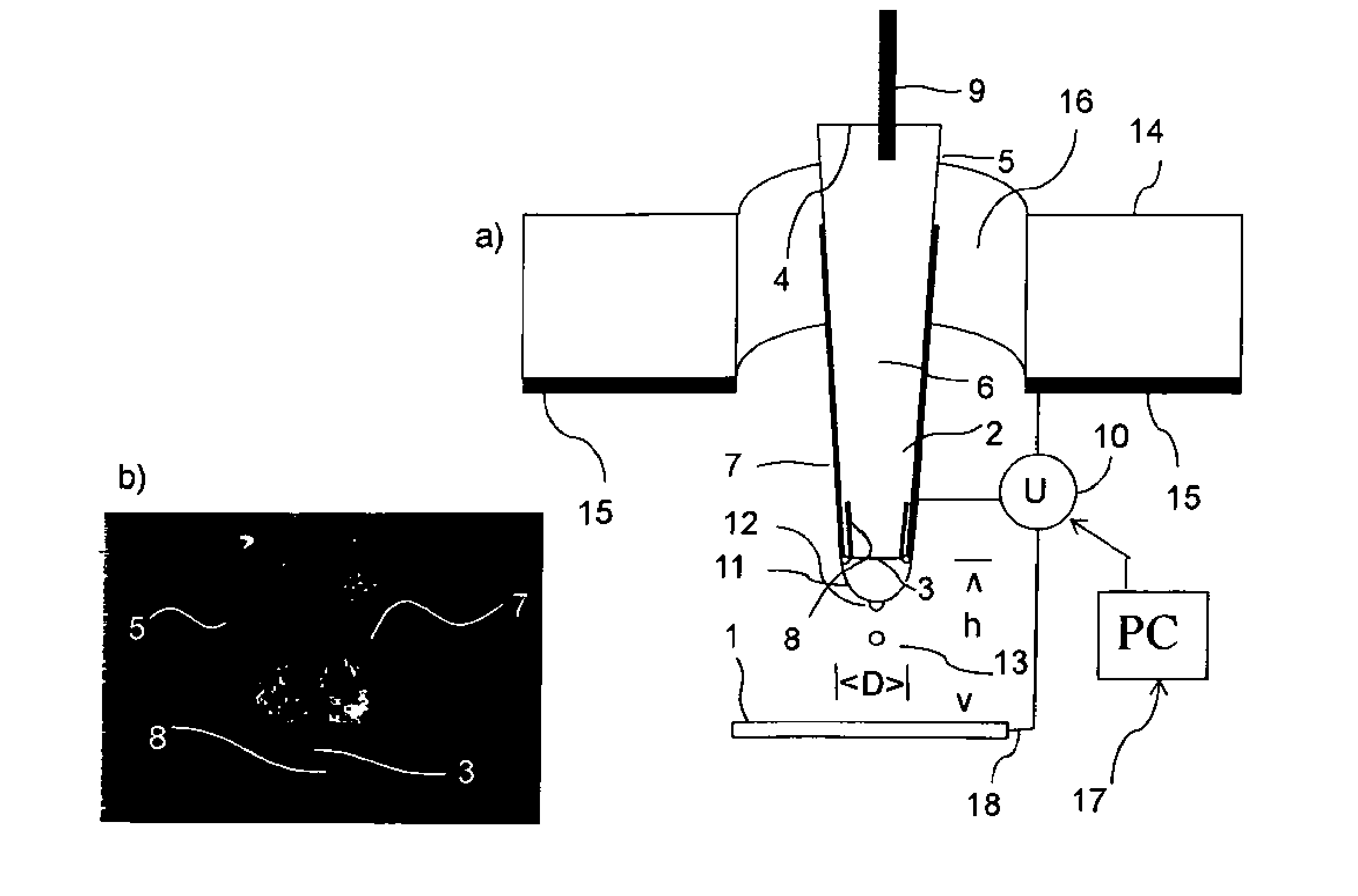
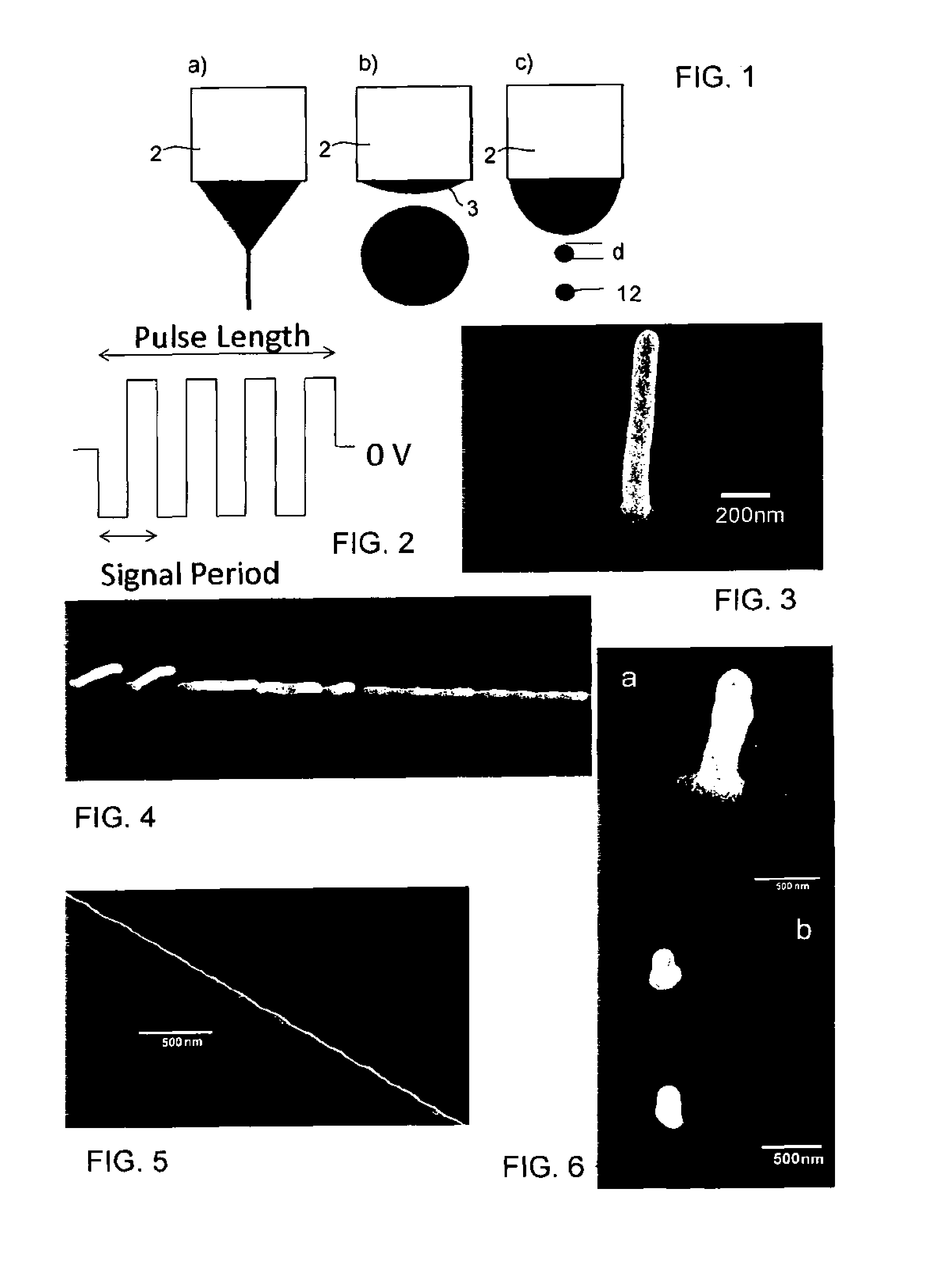
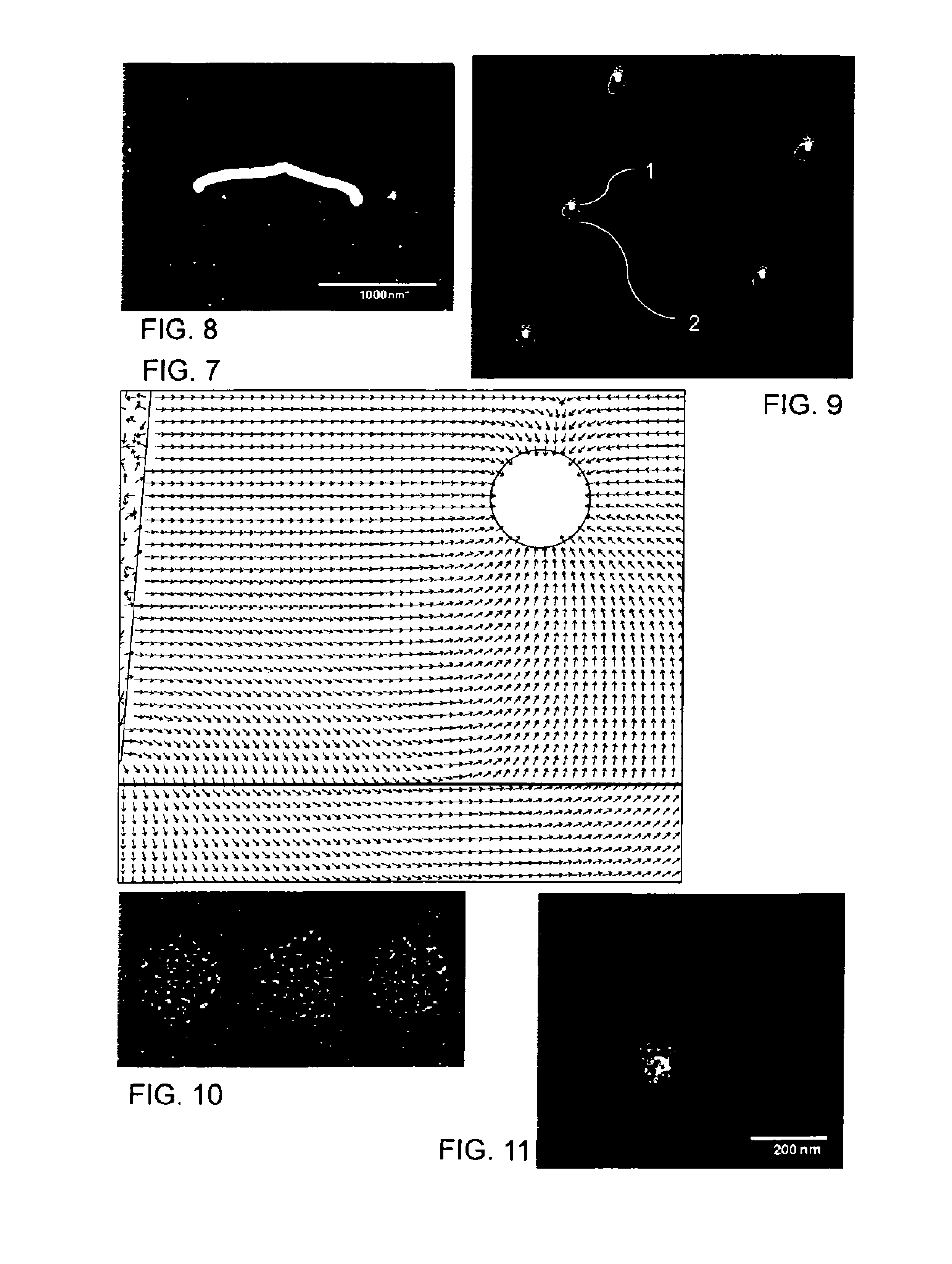
[0107]The section illustrates the proposed printing of 3D submicron structures. In the setup a gold-coated nozzle is filled with and in electrical contact to an ink. An electrical potential is applied between the nozzle and a counter electrode in and / or on and / or below and / or above a substrate to be printed on. Applying a high enough electrical potential between nozzle and counter electrode results in a regular ejection of monodisperse droplets. The nature and scaling relations of these droplets are considered in this work. Experiments demonstrate that the frequency strongly increases with the applied potential. The droplet diameter strongly decreases and converges to a final value once the charge relaxation time is longer than the time of liquid supply to the small droplet. For the used test system varying the applied potential between 100V and 400V increases the droplet frequency from 60 Hz to 100 kHz while the droplet diameter decreased from 1 micron to less than 100 nm. The mode...


PUM


Abstract

A method for the production of nano- or microscaled ID, 2D and / or 3D depositions from an solution (6), by means of a liquid reservoir (2) for holding the ink with an outer diameter (3,D) of at least 50 nm, is proposed, wherein there is provided an electrode (7,8 or 9) in contact with said ink (6) in said capillary (2), and wherein there is a counter electrode in and / or on and / or below and / or above a substrate (15) onto which the depositions are to be produced, including the steps of: i) keeping the electrode (7, 8, 9) and the counter electrode (15, 18) on an essentially equal potential; ii) establishing a potential difference between the electrode (7, 8, 9) and the counter electrode (15, 18) leading to the growth of an ink meniscus (1) at the nozzle (3) and to the ejection of droplets (13) at this meniscus with a homogeneous size smaller than the meniscus size (11) at a homogenous ejection frequency; keeping the voltage applied while the continuously dried droplets leave behind the dispersed material which leads a structure to emerge with essentially the same diameter as a single droplet, wherein the distance between the substrate (1) and the nozzle (3) is smaller than or equal to 20 times the meniscus diameter at least at the moment of nano-droplet ejection (12); wherein the conductivity of the ink (6) is high enough to stabilize the liquid meniscus during droplet ejection;

Description

TECHNICAL FIELD[0001]The present invention relates to methods for the production of 1D, 2D and / or 3D depositions from a liquid loaded with nanoparticles or other solid-phase nano-compounds stably dispersed in a solvent, by means of a nozzle-ended container for holding the liquid, wherein there is provided an electrode in contact with said liquid at said nozzle or in said container, and wherein there is a counter electrode in and / or on and / or below and / or above a substrate onto which the depositions are to be produced.PRIOR ART[0002]The controlled and spatially resolved deposition of pigmented liquids onto surfaces is of interest in a large variety of fields, in particular in the field of printing, the generation of conductor tracks or other functional entities for micro devices (printed electronics), especially for flexible devices and in the field of biological and / or chemical testing and substance / sample handling, for the production of photonic devices like photonic crystals or pl...

Claims


Application Information

Patent Timeline
Patent Type & Authority Applications(United States)
IPC IPC(8): B81C99/00
CPCB81C99/00B81C2201/0184B82B3/0019B81C1/00126H01L21/4867B81C99/0095
Inventor GALLIKER, PATRICKSCHNEIDER, JULIANPOULIKAKOS, DIMOSSANDOGHDAR, VAHIDEGHLIDI, MOHAMMAD HADI
Owner ETH ZZURICH
Learn More