

Organic compound for organic electroluminescent device
a technology of organic electroluminescent and compound, which is applied in the direction of luminescent compositions, organic chemistry, thermoelectric devices, etc., can solve the problems of unsatisfactory use practice of blue emitting materials for shorter half-life time and higher driving voltage, and achieve shorter half-life time, higher driving voltage and power consumption, and shortening the effect of half-life tim
- Summary
- Abstract
- Description
- Claims
- Application Information
AI Technical Summary
Benefits of technology
Problems solved by technology
Method used
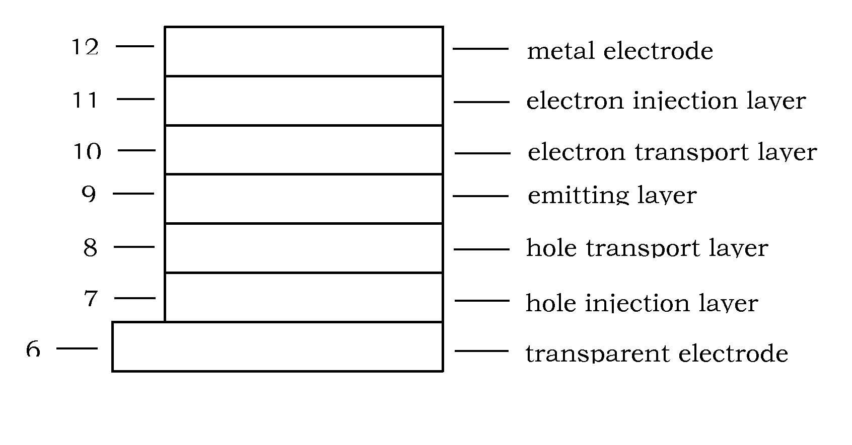
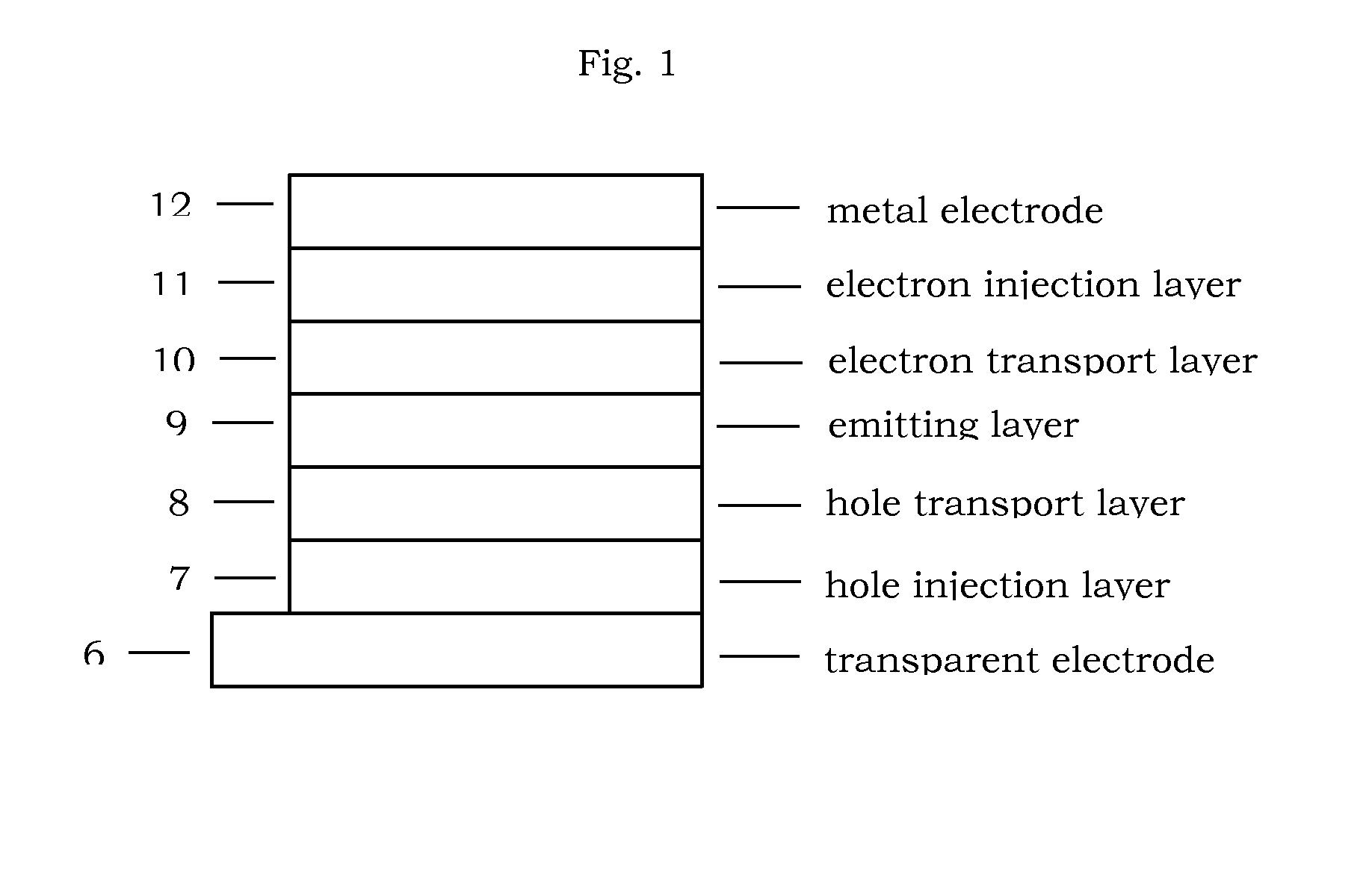
Image

Examples
example 1
Synthesis of Compound A-1
Synthesis of 4-fluoronaphthalen-1-ylboronic acid
[0016]
[0017]A three-necked 250 mL flask fitted with two dropping funnels, magnetic stirring bar, and low-temperature thermometer was charged with 2-bromo-4fluoronaphthalene (10.9 g, 48.3 mmol) under nitrogen. Dry THF (100 mL) was added, and the solution was cooled to −78° C. To this solution was added n-butyllithium (33.2 mL of a 1.6 M solution, 53.1 mmol) dropwise through the first dropping funnel. The solution was stirred at −78° C. for 2 h whereupon trimethyl borate (6.0 g, 57.9 mmol) dissolved in 10 mL of dry THF was added dropwise through the second dropping funnel. The solution was allowed to warm to room temperature overnight. The reaction was quenched with dilute HCl (20%, 70 mL), and the reaction mixture was concentrated at 30° C. to 50% of its original volume by rotary evaporation and poured into H2O. The resulted biphasic solution was extracted with ethyl acetate (2×100 mL). The organic phases soluti...
example 2 to example 4
Synthesis of Compound A-2 to A-4
[0027]The synthesis of procedures are the same process with EXAMPLE 1, the product yield (%) of the final step are individually 75.6% for Compound A-2, 89.8% for compound A-3 and 46.5% for A-4.
example 5
Synthesis of Compound A-5
Synthesis of 2-(4-bromonaphthalen-1-yl)thiophene
[0028]
[0029]A mixture of 28.6 g (100 mmol) of 1,4-dibromonaphthalene, 15.35 g (120 mmol) of thiophen-2-ylboronic acid, 2.31 g (2 mmol) of tetrakis(triphenyl phosphine)palladium, 75 ml of 2M Na2CO3, 150 ml of EtOH and 300 ml toluene was degassed and placed under nitrogen, and then heated at 100° C. for 4 h. After finishing the reaction, the mixture was allowed to cool to room temperature. The organic layer was extracted with ethyl acetate and water, dried with anhydrous magnesium sulfate, the solvent was removed and the residue was purified by column chromatography on silica(hexane-dichloromethane) to give product (21.1 g, 73 mmol, 73%) as a white solid.
Synthesis of 4,4,5,5-tetramethyl-2-(4-(thiophen-2-yl)naphthalene -1-yl) -1,3,2-dioxaborolane
[0030]
[0031]A mixture of 21.1 g (73 mmol) of 2-(4-bromonaphthalen-1-yl)thiophene, 24.1 g (95 mmol) of bis(pinacolato)diboron, 1.7 g (1.46 mmol) of tetrakis(triphenylphosph...
PUM
| Property | Measurement | Unit |
|---|---|---|
| Efficiency | aaaaa | aaaaa |
Abstract
Description
Claims
Application Information