Partially porous bone implant keel

Active Publication Date: 2014-09-11
HOWMEDICA OSTEONICS CORP
View PDF8 Cites 30 Cited by
  • Summary
  • Abstract
  • Description
  • Claims
  • Application Information

AI Technical Summary

Benefits of technology

[0018]The porous portion of the keel encourages the bony ingrowth for metaphyseal load transfer and the solid portion of the keel provides the device alignment and stability. A fully porous keel section also provides

Problems solved by technology

This allows for the potential to lose large quantities of bone stock, when the implant is removed under conventional means.
Other disadvantages of the current removal techniques include increased metal debris at and around the surgical site, increased heat and increased time in the operating room (OR).
The replacement of that bearing with a stiff metal component shields the bone from much of the load in the anterior and posterior regions, leading to a lack of remodeling and ultimately, resorption.
Both methods have yielded positive effects, but present obvious disadvantages when used with solid implants.
However

Method used


Image

  • Partially porous bone implant keel
  • Partially porous bone implant keel
  • Partially porous bone implant keel

Examples


example

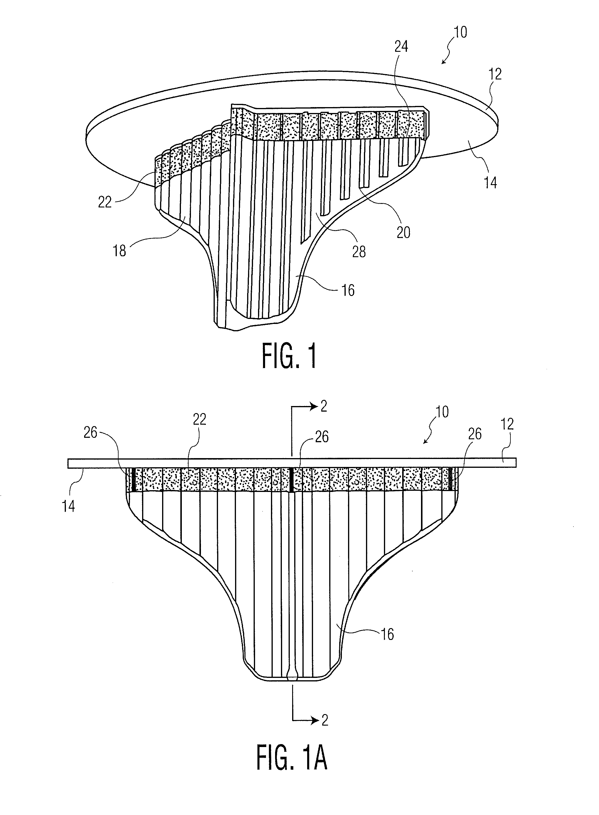
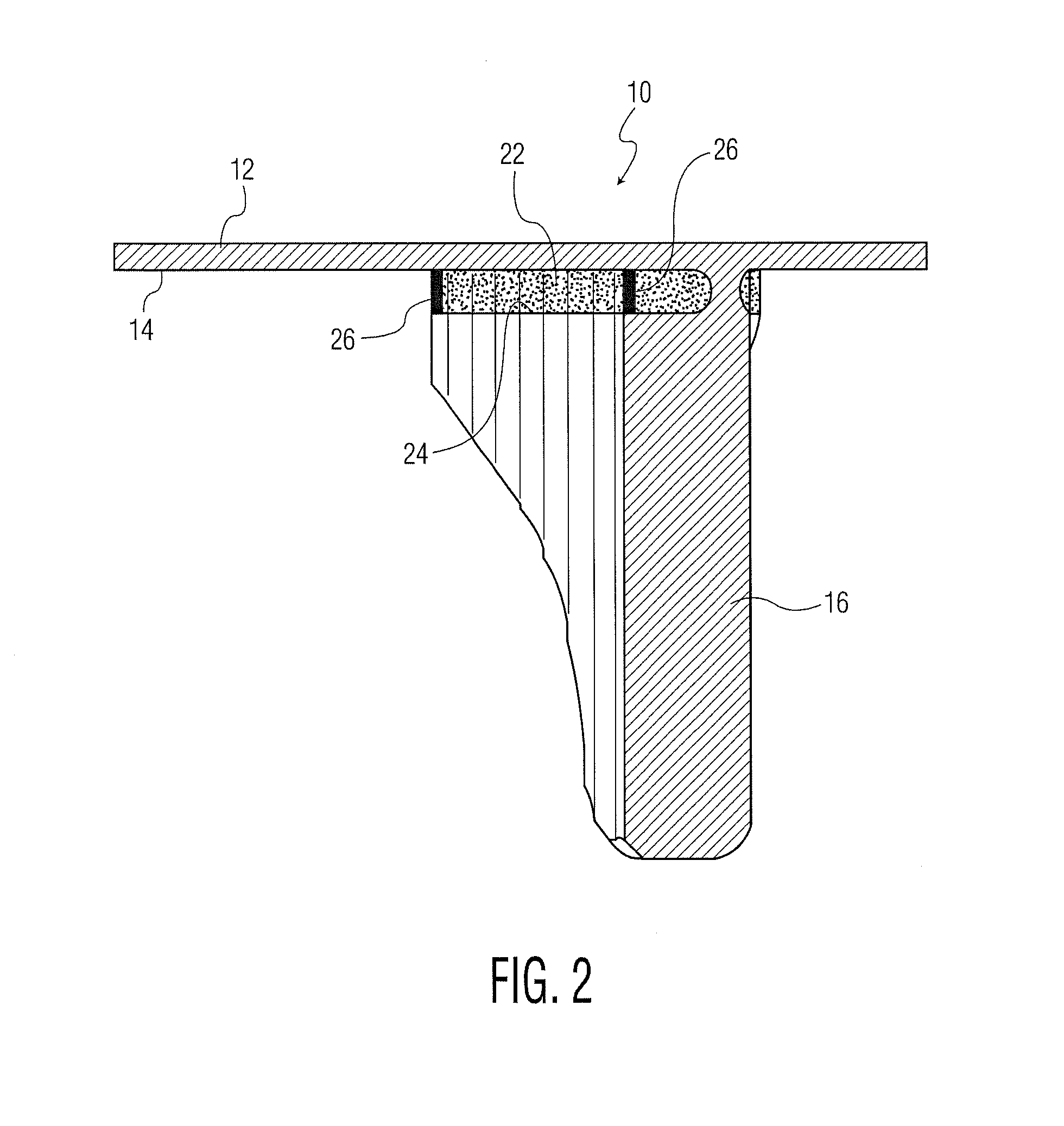
[0089]The following is a method for making a partially porous implant and porous area by near-net shape building of a modular tibial tray component 10 of FIGS. 1-2 via additive (layer-by-layer) manufacturing.

[0090]A solid (non-porous) tray preform (e.g., forging) is partially or entirely machined to the final implant shape for example a tibial baseplate.

[0091]A layer-by-layer (additive manufacturing) direct build onto the solid tray preform 12 (e.g., Selective Laser Melting-SLM).

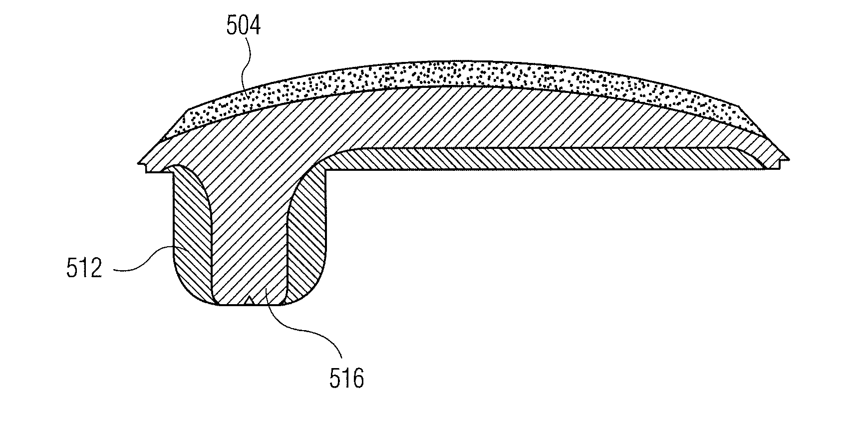
[0092]The construct is a hybrid SLM-built structure that is a combination of (a) porous SLM with a preferred porosity between 4-80% and a pore size in the range of 10 μm to 1000 μm, in which 100-400 μm is preferred for bone ingrowth and a “fully dense” SLM-built material that is less than 20% porous. This porous structure 22 is between 1 and 5 mm thick followed by a solid keel section 16. Both structures 16 and 22 may have a v-shape.

[0093]The SLM-built structure consists of a fully porous area 22 and a bone ...


PUM


Abstract

A method for removing a stem portion of an orthopedic implant from a bone comprises exposing an implanted orthopedic implant having a body portion, a stem portion interconnected to the body and a porous metal section forming an interconnection between the body and the stem portion. A cutting tool is mounted on a holder connected to an exposed surface of the orthopedic implant. The porous section is aligned with the cutting tool mounted on the holder. The entire porous section is cut by moving the cutting tool therethrough in a direction transverse to the stem portion axis. The implant body portion is then removed and then the stem portion is removed from the bone. The cutting tool may be a saw or chisel which may be mounted on a guide fixed to the body portion.

Description

BACKGROUND OF THE INVENTION[0001]Current keel implant devices, such as tibial components, are solid with high stiffness are commonly associated with diaphyseal load transfer or stress shielding. This invention provides a porous section for allowing bone ingrowth and a reduced stiffness keel device for more anatomical load transfer. In addition, the porous section allows easier removal of the implant during revision procedure.[0002]The present invention also relates to a device having two different porous surfaces attached directly or indirectly to one another and a method for forming the same. The two porous surfaces may be separated by a solid or fully dense (non-porous) layer.[0003]The present application is particularly directed toward a method of forming porous or partially porous metallic structures having different porosities for bone ingrowth and soft tissue ingrowth or attachment. Porous structures may also be formed for polymer attachment.[0004]One method of producing the d...

Claims


Application Information

Patent Timeline
IPC IPC(8): A61F2/38
CPCA61F2002/30879A61F2002/30891A61F2002/3093A61F2002/3097A61F2002/30454A61F2/30749A61F2/389A61F2002/3092A61F2002/30451A61F2002/30013A61F2002/30878A61F2002/30892A61F2002/30884A61F2/30907A61F2/3094Y02P10/25A61F2/3877A61F2002/30011A61F2/30767A61F2002/4619A61F2002/30322A61F2002/4641A61F2/461A61F2002/30179
Inventor WANG, AIGUOPOGGIE, MATTHEW P.DONG, NICHOLAS NAI GUANG
Owner HOWMEDICA OSTEONICS CORP
Why Eureka
Try Eureka