Tyer carburetion process

a carburetion process and gasifier technology, applied in the field of fluidized bed gasifiers, can solve the problems of insufficient processing of most starved-air gasifiers, inability to meet the requirements of use, and high cost, so as to achieve accurate control of fuel movement, reduce the pitch of the auger, and maximize the exposure to oxidation and/or gasification

Inactive Publication Date: 2014-09-25
TYER SR ROBERT CLARK
View PDF8 Cites 5 Cited by
  • Summary
  • Abstract
  • Description
  • Claims
  • Application Information

AI Technical Summary

Benefits of technology

[0009]One of the unique features within the Tyer Carburetion Process auger gasifier system is its auger. Fuel enters the primary auger gasifier at a continuous controlled rate and is shaped into a pile by the first auger flight, then pushed and tumbled through the gasifier chamber by the auger. As the auger moves the fuel through this horizontal gasifier cylinder, it stirs the material to maximize exposure for oxidation and / or gasification; this is accomplished by reversing the direction the auger is traveling and creating a void between the auger flight and the gasifying fuel then reversing the direction again thus exerting force o the char and pushing it into the un-gasified fuel. The pitch of the auger can decrease, along the path of material flow to accommodate the decrease of fuel bulk and retention time as the material gasifies. The use of an auger to convey fuel through the gasification cycle is an improvement, which results in very accurately controlled movement of fuel through the gasification chamber, in comparison to alternative rotary kiln incinerators. This ability to manage fuel-bed configuration permits control of forced-draft combustion air so as to minimize combustion and gasify nearly all the carbonaceous fuel without complete combustion taking place, thereby allowing the gasifier to operate at what is a uniformly moderate temperature from auto-ignition to desired exit gas temperature, as well as, supplying char and / or steam to the secondary auger gasifier.
[0010]The combination of fuel bed auger agitating, stirring with air injection produce precise temperature control evidencing the Tyer Carburetion Process auger gasifier system several advantages over prior technology: Reliability and clean operation; high throughput; low gasifier temperature, longer material life (refractory and auger); fully automatic control; and the ability to combust a wide variety of heterogeneous solid fuels. However, several of these advantages are further strengthened by the addition of a substrate of appropriate granular materials to act as an “air bearing” in the auger combustor / gasifier chamber, and to aid in the diffusion of gasification air through the material being burned as more fully described in U.S. Pat. No. 6,349,658.
[0011]Still, while the auger combustor / gasifier described in the foregoing patents offers a cost-effective approach to clean, efficient gasification, I have found that various innovative improvements, as further taught herein, support and facilitate its operations and of efficiency. These improvements include provision of a vertically elongated (“oblong”) primary combustor / gasifier chamber with an auger that can move up and down allowing for large amounts of fuel input when necessary. This improvement, in turn, requires and / or is facilitated by provision for simultaneous elevation adjustments of the auger and bed darn to assure that fuel material is processed in degrees from the top downward without sweeping massive amounts of the fluidized bed materials towards the output end of the chamber.
[0012]Another improvement involves provision for optional independent pressurization of the primary auger gasifier and / or of the secondary auger gasifier, allowing substantial increase in the fuel processing speed through the gasifier. Because the Tyer Carburetion Process utilizes low gasification temperatures, high convection rates and radiative heat transfer, the heat, which is normally lost from the bulk bed material, is now providing to the fuel sufficient ignition energy to evaporate moisture, heat the ash and gasify the remaining fuel without significantly changing the instantaneous bed temperature. My Biomass bubbling bed operates sub-stoichiometrically, or below the ideal gas laws because all the available oxygen is used. If an increase of oxygen was allowed into the auger gasifier chamber a greater portion of the fuel would become oxidize leading to an increase of the amount of bed heat that would be released; contrary to this, lower oxygen levels have the reverse effect.
[0013]Because I can control both the duration and the direction of the auger cycles, use a lower gasification temperature, a higher convection and heat transfer rate, I can create a more efficient and cost effective system which is well adapted to meet the continuing needs of our modern technological civilization for elimination of waste, such as but not limited too, RDF & MSW while producing clean environmentally sound sources of alternative energy therefrom.

Problems solved by technology

The current rising costs of such fuels and concerns over the adequacy of their supply in the future has made them a less desirable energy source and has led to an intense investigation of alternative sources of energy.
Unfortunately, most starved-air gasifiers, as originally developed and operated, were not entirely satisfactory in processing the gasifiable elements of the fuel at high throughput while not producing noxious emissions.
This problem resulted, in part, from the use of such gasifiers to burn a wide variety of fuels, including many that were non-homogeneous, such as household municipal solid waste (MSW) and commercial refuse-derived fuel (ROF).
While the pollution problem can be solved to a degree by the utilization of scrubbers and other antipollution devices, such mechanisms are very expensive and their cost may militate against the use of alternative energy sources previously described.

Method used


Image

  • Tyer carburetion process

Examples


embodiment one

; OPERATIONAL DESCRIPTION

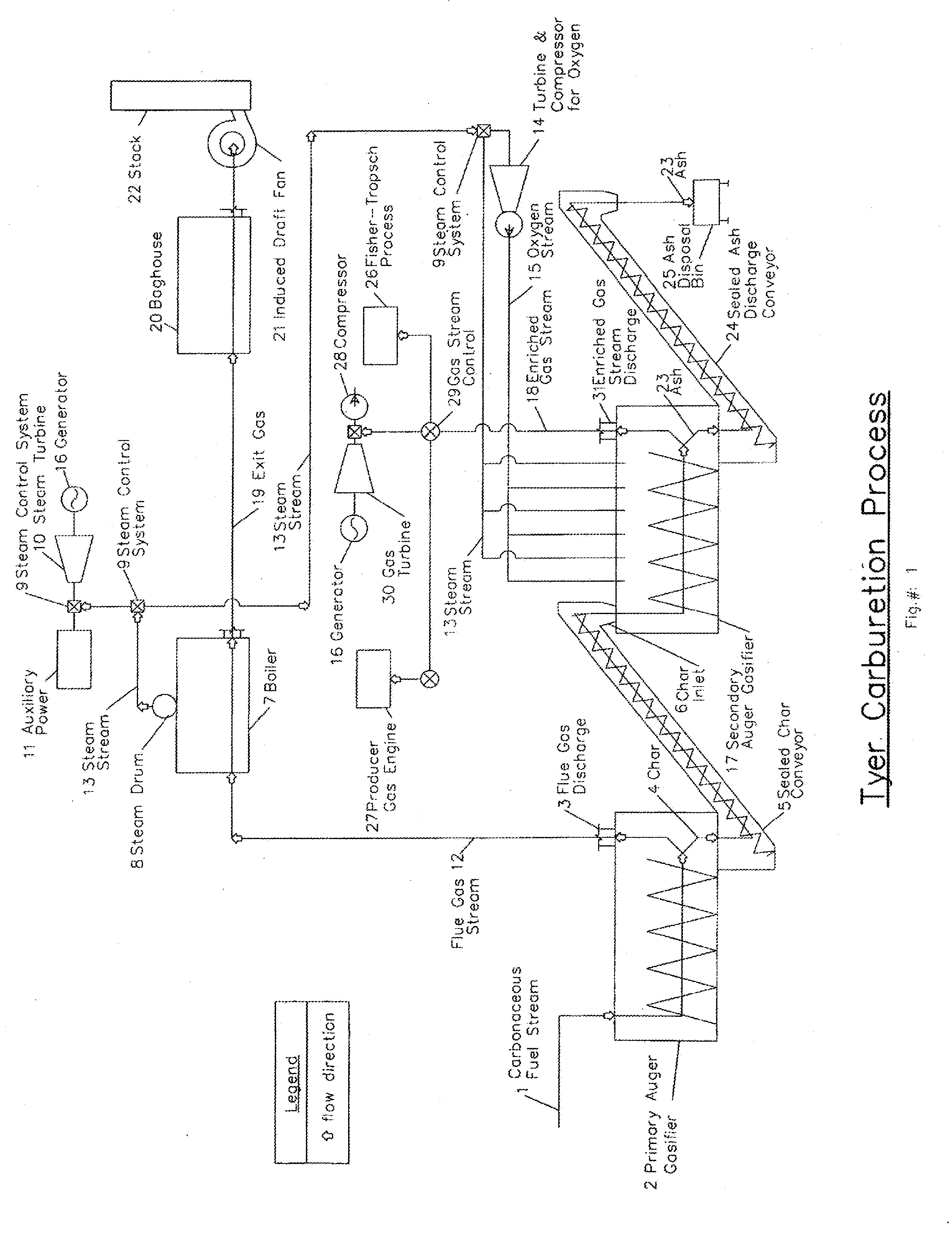
[0048]A carbonaceous fuel stream is introduced into the primary auger gasifier, advanced, agitated and tumbled by an auger, partially gasified and creates a flue gas stream and char product. The char product is collected from the primary auger gasifier, conveyor and delivered into the secondary auger gasifier. As said primary auger gasifier produces the flue gas stream that exits the flue gas discharge from the primary auger gasifier, said gases are directed to the boiler for steam production. After leaving said boiler, the flue gas stream, now an exit gas is cleaned and discharged. Concurrently, the steam stream also exiting the boiler steam drum, controlled by the steam control system directs steam stream to provide steam either into the steam turbine, which powers an electrical generator, and / or for auxiliary power. When required, for the water gas shift reaction, steam control system can direct both the steam stream into the secondary auger gasifier's do...


PUM

PropertyMeasurementUnit
energyaaaaaaaaaa
temperatureaaaaaaaaaa
forceaaaaaaaaaa

Abstract

A means for improving prior art combined cycle combustor and / or gasifiers and / or plural thermodynamic cycle gasification systems by introducing and utilizing an auger for the continuous feeding, agitation, tumbling, advancement and discharge of heterogenous carbonaceous fuel. In addition to the aforementioned improvement, I have included provisions for Fontana's water gas shift reaction utilizing refectory embedded down-tubes that convey steam and oxygen into and through the chambers fluidized bed.

Description

CROSS-REFERENCE TO RELATED APPLICATIONS[0001]This application claims subject matter disclosed in a provisional application filed Jan. 14, 2009, Ser. No. 61 / 205,055 entitled “Combined Cycle Gasifier” and a non-provisional application filed Feb. 20, 2009, Ser. No. 12 / 378,864, entitled “Improved Auger Combustor”, and is a continuation of a non-provisional application filed Jan. 19, 2010, Ser. No. 12 / 657,226, entitled “Tyer Carburetion Process.” The benefit under 35 USC 309(e) of the United States provisional application is hereby claimed, as are the priority benefits of the other applications named, the aforementioned applications being hereby incorporated herein by reference.BACKGROUND AND SUMMARY[0002]The invention relates generally to fluidized bed gasifiers and to the production of gasified fuel via and / or in conjunction with the gasification of solid fuels in a fluidized bed gasifier featuring a rotating auger conveyor. More particularly, it deals with improvements to gasifiers th...

Claims


Application Information

Patent Timeline
Patent Type & Authority Applications(United States)
IPC IPC(8): C10J3/72
CPCC10J3/007C10J3/721C10B7/10C10B49/02C10B53/00C10B53/02C10J2300/0916C10J2300/092C10J2300/0959C10J2300/0976C10J2300/165C10J2300/1659C10J2300/1675C10J2200/158C10J3/62Y02P20/145Y02E20/18Y02E50/30Y02E50/10
Inventor TYER, SR., ROBERT CLARK
Owner TYER SR ROBERT CLARK
Why Eureka
Try Eureka