
Lithographic printing plate comprising a laminated substrate

a technology of laminated substrates and printing plates, applied in the direction of printing processes, film/foil adhesives, weaving, etc., can solve the problems of preventing their wide acceptance in the industry, affecting the quality of printed images, and difficult to recycle substrates

Inactive Publication Date: 2014-10-16
MYLAN GRP
View PDF4 Cites 3 Cited by
  • Summary
  • Abstract
  • Description
  • Claims
  • Application Information

AI Technical Summary

Benefits of technology

The present invention provides a method for making a lithographic printing plate that can be easily integrated into existing manufacturing processes. The method involves adding a lamination step to an existing process, reducing the thickness of the aluminum layer and cost of the printing plate. The invention also involves using an adhesive layer to bond the base layer to the aluminum layer, which adds structural integrity to the printing plate. The invention also describes methods for producing the lithographic printing plate by providing an aluminum layer with an aluminum oxide layer and an image layer, or by adding an adhesive layer to a base layer. The invention also includes a description of specific embodiments for making the lithographic printing plate.

Problems solved by technology

However, these can de-laminate upon use on press and are thus generally useful only for short run printing.
More importantly, these substrates are not readily recyclable, which prevented their wide acceptance in the industry.
In addition, such substrates have a tendency to stretch upon use, which causes distortion of the printed image.
However, these substrates are generally recyclable.
This increases the handling cost as the interleaving paper has to be removed for the plates to be loaded on a printing press.
Similarly, it is noted that it is very difficult to cut a stack of printing plates to size without using interleaving paper.

Method used


Image

  • Lithographic printing plate comprising a laminated substrate
  • Lithographic printing plate comprising a laminated substrate
  • Lithographic printing plate comprising a laminated substrate

Examples


example 1

Positive Printing Plate Comprising a Hot-Melt Adhesive and its Mechanical Processing

[0244]Manufacture. This printing plate was produced following a process similar to that shown in FIG. 4. However, there was no coating of a second image layer or overcoat layer. In other words, steps 111 and 112 of FIG. 4 were omitted.

[0245]An aluminum substrate (see the Glossary above) was subjected to the following electrolytic, coating and drying process:[0246]1) Washing with an aqueous alkaline solution containing sodium hydroxide (3.85 g / l) and sodium gluconate (0.95 g / l) at 65° C.;[0247]2) Neutralizing with aqueous hydrochloric acid (2.0 g / l);[0248]3) Washing with water;[0249]4) Electrolytic graining in an aqueous electrolyte containing an aqueous solution of hydrochloric acid (8.0 g / l) and acetic acid (16 g / l), using carbon electrodes at 25° C. The current and charge density were 38.0 A / dm2 and 70.0 C / dm2, respectively;[0250]5) Desmuting with an aqueous sodium hydroxide solution (2.5 g / l);[025...

example 2

Positive Printing Plate Comprising a Coated Adhesive and its Chemical Processing Using an Alkaline Media

[0268]Manufacture.

[0269]This printing plate was produced following a process similar to that shown in FIG. 5. However, there was no coating of a second image layer or overcoat layer. In other words, steps 211 and 212 of FIG. 5 were omitted.

[0270]The manufacture of this printing plate was similar to that described in Example 1, except for the following. A BOPET base film was corona treated. An adhesive solution containing 5% Elastack® 1000 and 95% Dowanol PM was coated on the BOPET base film using a slot-die coater. This solution was then dried at 120° C. using hot air to produce an adhesive layer. The adhesive coated BOPET was then laminated on the back of the aluminum layer.

[0271]Use.

[0272]After one week storage, the plate was imaged with a plate-setter (PlateRite 8600S, available from Screen, Japan) at an energy density 150 mJ / cm2. The imaged plate was developed with GSP85 devel...

example 3

Positive Printing Plate Comprising a Coated Adhesive and its Chemical Processing Using an Acidic Media

[0275]Manufacture and Use.

[0276]This printing plate was identical to that of Example 2 except that Elastack® 1000 was replaced by Elastack® 1020. The obtained printing plate had the same prepress and press characteristics as that described for the printing plate of Example 2. No delamination was observed during imaging, development and printing.

[0277]Chemical Processing in View of Recycling.

[0278]The separation of the BOPET base layer from the aluminum layer was effected by immersing the used plate into an aqueous solution containing 1M hydrochloric acid at 35° C. for 1 hour. The adhesive layer dissolved and the BOPET base film was peeled from the aluminum layer by a home-made mechanical peeling device.


PUM

PropertyMeasurementUnit
Tgaaaaaaaaaa
Tgaaaaaaaaaa
thicknessaaaaaaaaaa

Abstract

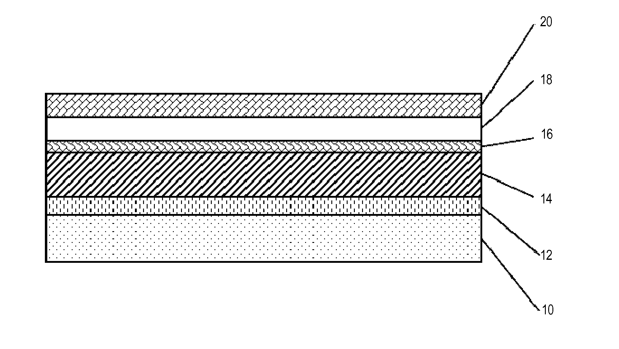
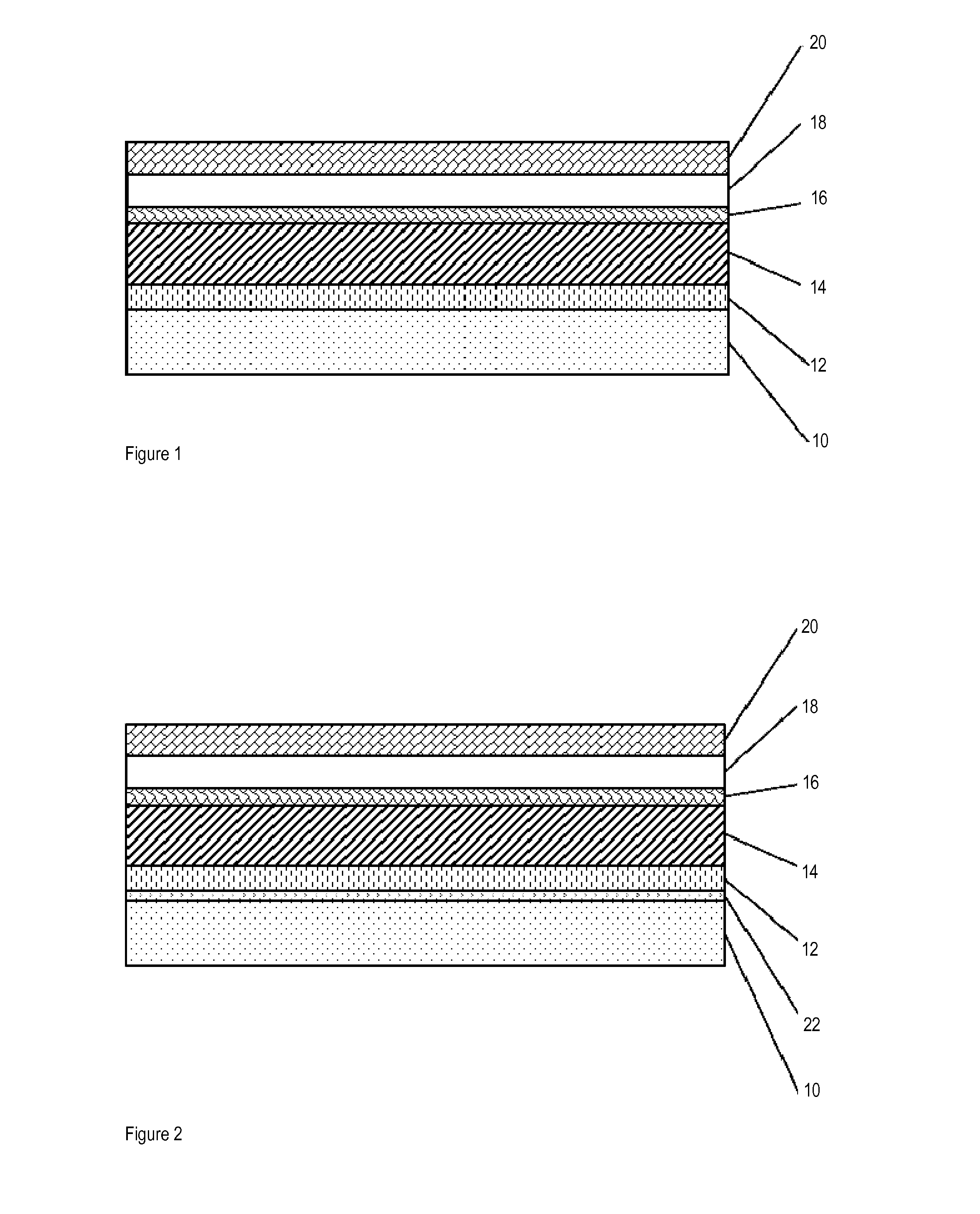
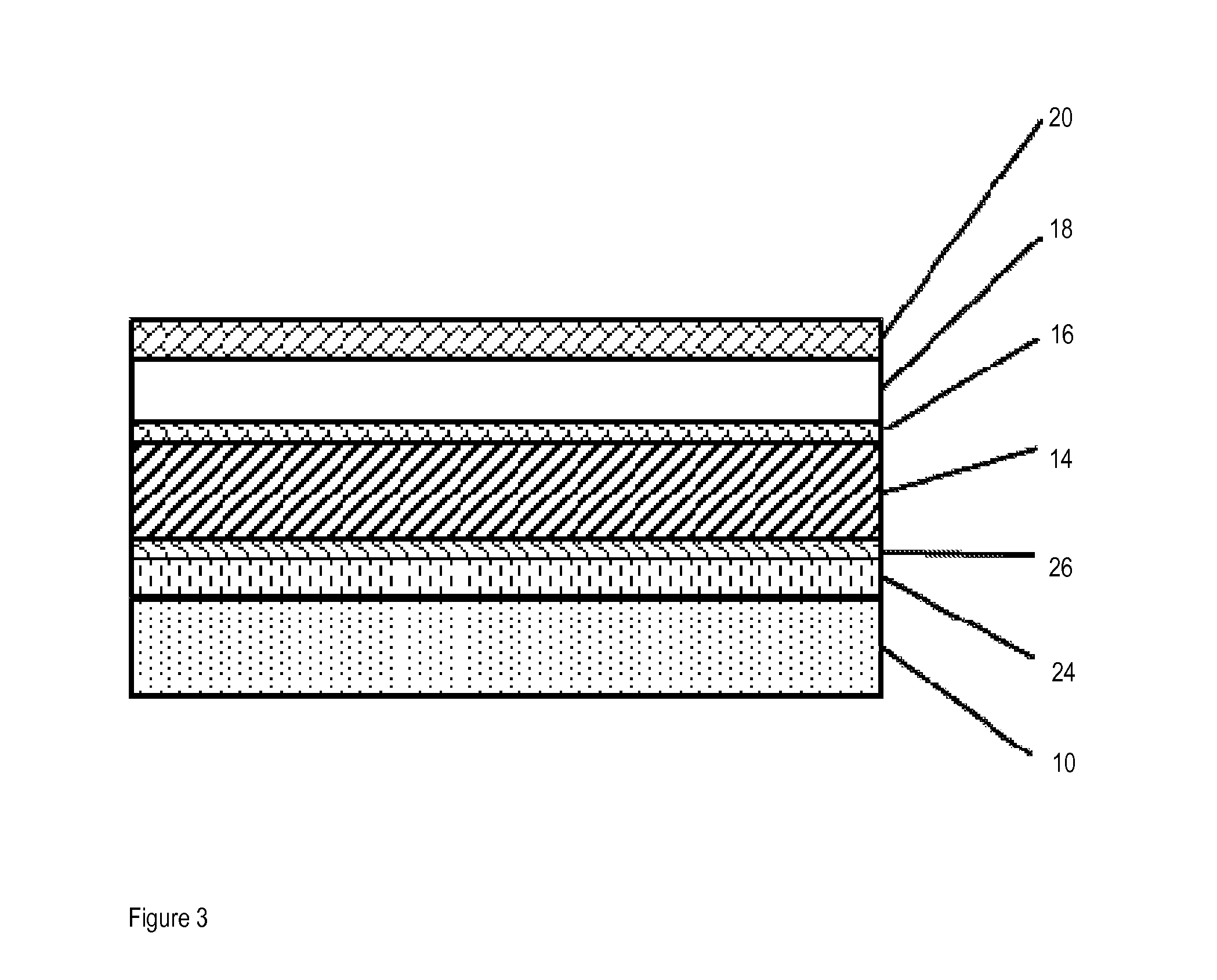
A laminated lithographic printing plate comprising an aluminum layer having a first side and a second side, an aluminum oxide layer coating the first side aluminum layer, optionally a second aluminum oxide layer coating the second side of the aluminum layer, an image forming layer coating the first aluminum oxide layer, an adhesive layer adhering to the second side of the aluminum layer or to said second aluminum oxide layer when second aluminum oxide layer is present, and a base layer coating the adhesive layer is provided.

Description

CROSS REFERENCE TO RELATED APPLICATIONS[0001]This application claims benefit, under 35 U.S.C. §119(e), of U.S. provisional application Ser. No. 61 / 810,303, filed on Apr. 10, 2013. All documents above are incorporated herein in their entirety by reference.FIELD OF THE INVENTION[0002]The present invention relates to lithographic printing plates incorporating a laminated substrate. More specifically, the present invention is concerned with such printing plates where the laminated substrate can be delaminated in view of recycling its various layers.BACKGROUND OF THE INVENTION[0003]In lithographic printing, a printing plate is mounted on the cylinder of a printing press (typically using clamps on two opposite sides of the printing plate). The printing plate carries a lithographic image on its surface and a printed copy is obtained by applying ink to the image and then transferring the ink from the printing plate onto a receiver material, which is typically a sheet of paper. Generally, th...

Claims


Application Information

Patent Timeline
Patent Type & Authority Applications(United States)
IPC IPC(8): B41N1/08
CPCB41N1/083B41N1/086B41C1/1016B41C2201/06B41C2201/14C09J7/385G03F7/094Y10T428/1443Y10T428/1495Y10T428/269Y10T428/2804Y10T428/2891Y10T428/31605Y10T428/31609Y10T428/31663Y10T428/31692Y10T442/656B41C1/10C09J2433/00
Inventor NGUYEN, MY T.DANG, THUONG T.PHAN, KHAI N.
Owner MYLAN GRP
Learn More