
Safety brake system for trailers

a brake system and trailer technology, applied in the direction of braking system, towed device, exhaust gas recirculation, etc., can solve the problems of reducing efficiency and/or power output, requiring more expensive aftertreatment subsystems, and reducing no/sub>x/sub>levels, etc., to reduce the overall pumping work, and reduce the effect of operation efficiency

Active Publication Date: 2014-10-23
MERCURE ROGER
View PDF9 Cites 0 Cited by
  • Summary
  • Abstract
  • Description
  • Claims
  • Application Information

AI Technical Summary

Benefits of technology

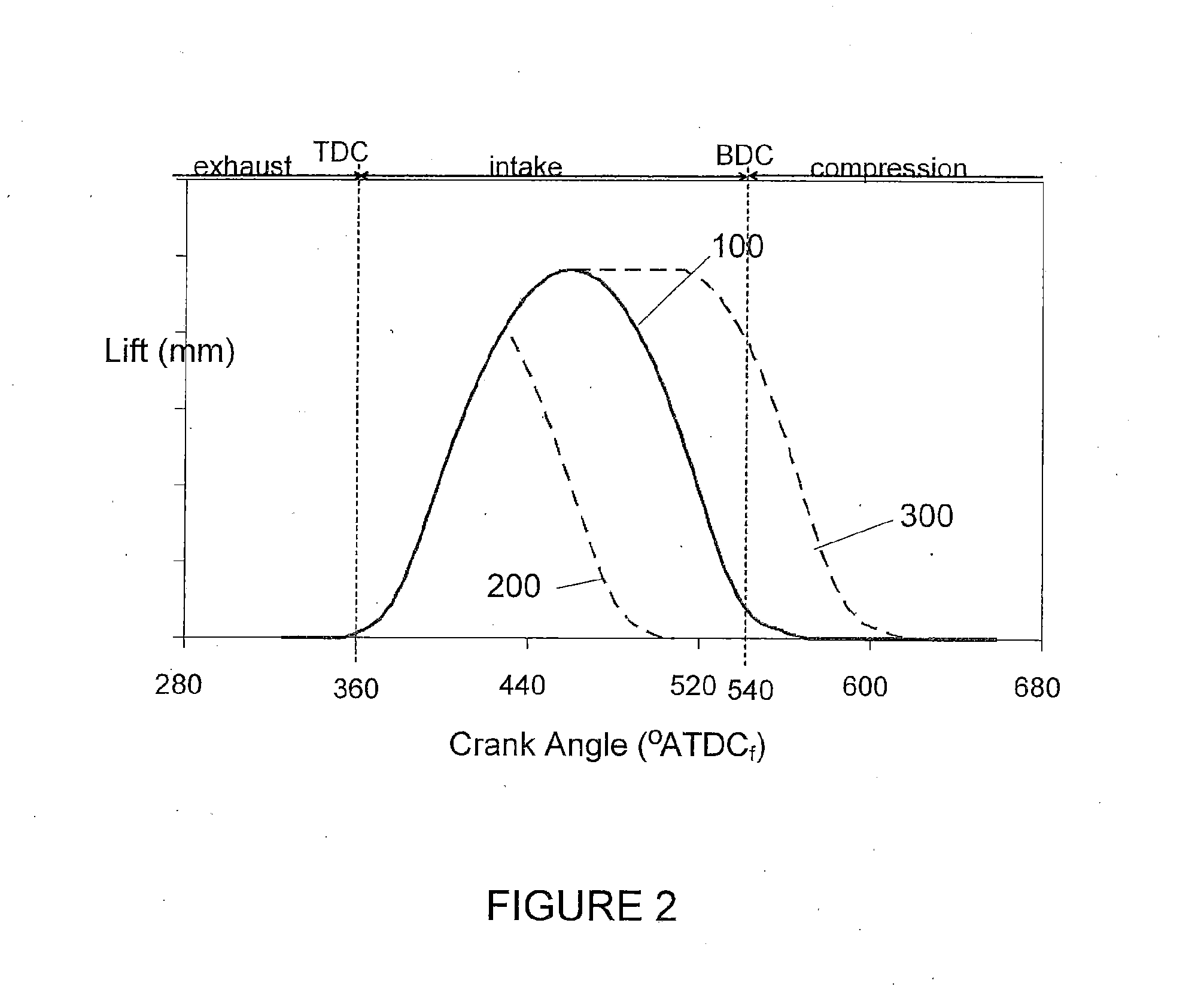
The present invention provides an engine and methods for operating it that can control pumping losses when operating at low loads. This is achieved by controlling the timing of the intake valves and the intake valve lift, deactivating at least one engine combustion chamber, or opening a bypass valve in the engine's exhaust gas system. The engine controller can also deactivate one or more cylinders and introduce air and gaseous fuels in a reduced number of cylinders for efficient operation. The engine design uses a three-way catalyst exhaust treatment system and means for controlling the air / fuel ratio of the combustion mixture comprising a throttle, variable valve actuation strategies, or pulse width modulation of the gaseous fuel injector. The invention provides a more cost-effective and efficient engine design.

Problems solved by technology

With such engines, the most common approach for igniting a gaseous-fuel / air mixture is to employ spark ignition because unlike liquid fuels like diesel, gaseous fuels are generally more difficult to ignite by compression ignition.
A disadvantage of lean burn engines is that the presence of excess oxygen in the exhaust gas exiting the combustion chamber makes a lean burn engine incompatible with modern three way catalyst aftertreatment subsystems, which means that a more expensive aftertreatment subsystem is required to reduce NOx levels.
Stoichiometric engines normally have lower compression ratios compared to lean burn engines, which normally results in lower efficiency and / or lower power output, but the combustion products are compatible with modern three-way catalyst aftertreatment subsystems so this has helped stoichiometric engines to meet recent emissions standards without requiring the more complex and more expensive aftertreatment subsystems needed by lean burn engines.
However, as noted previously, a charge consisting of gaseous fuel and air is difficult to ignite by compression alone without the use of an ignition assisting device, such as the ignition of a more readily ignited pilot fuel, such as a small amount of diesel fuel, or a glow plug or other hot surface.
However, this approach uses an excess amount of air since it does not employ a throttle and therefore it is not stoichiometric, and like lean burn engines, dual fuel engines require more complicated and expensive exhaust treatment to treat emissions.
However, this requires a more complicated and expensive fuel supply subsystem which can deliver both the primary gaseous fuel and the pilot fuel at injection pressures of at least 200 bar.
Accordingly, to comply with current emissions requirements in many jurisdictions, compared to stoichiometric engines, HPDI engines typically require a more complicated and expensive aftertreatment subsystem for treatment of the exhaust.
Even though internal combustion engines have undergone continuous improvement for more than a century, the combustion process in an internal combustion engine is complex and even now it is not fully understood.
There are many variables and combinations of features that have not been tried and without investigation by computer modeling and / or experimental testing, the effect of a previously untried combination can not be accurately predicted.

Method used


Image

  • Safety brake system for trailers
  • Safety brake system for trailers
  • Safety brake system for trailers

Examples


Embodiment Construction

)

[0041]For purposes of focus and brevity certain aspects of the embodiments that are conventional and well known to those familiar with gaseous fuelled engine technology are not described in detail.

[0042]In the prior art, certain terms have been used in different contexts and in different publications to have different meanings. Accordingly, in the context of this disclosure and the description of the present method and apparatus, the following terms are defined as follows:

[0043]“Stoichiometric” refers to situations pertaining to oxidant and fuel mixtures in which the total amount of oxidant is balanced with the total amount of fuel present such that both would be essentially completely consumed when combusted. Numerically the total oxidant / total fuel ratio is preferably 1±0.1 and more preferably 1±0.05.

[0044]“Normal” engine operation refers to the various routine modes of operation for the engine when operating in a steady state (for example: idle, light load, full load). Most of t...


PUM


Abstract

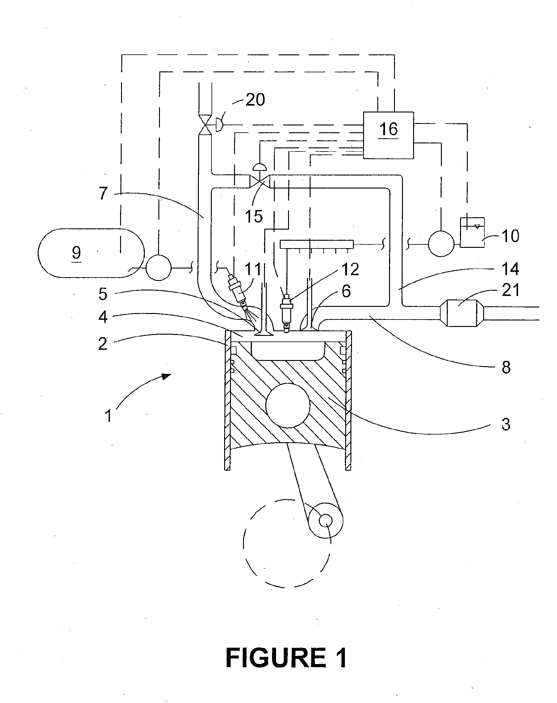
In a gaseous-fuelled stoichiometric compression ignition internal combustion engine, a pilot fuel is injected directly into the combustion chamber to help initiate a multi-point ignition. The engine provides performance improvements approaching those of high pressure direct injection engines but with less complexity because the gaseous fuel is introduced into the intake air subsystem at relatively low pressure and as a result of the stoichiometric combustion, the low oxygen content in the combustion products exiting the combustion chamber allows the use of a three-way catalyst instead of other after treatment arrangements normally associated with conventional compression ignition engines that require the addition of a reductant.

Description

FIELD OF THE INVENTION[0001]The present invention relates to a gaseous-fuelled stoichiometric compression ignition internal combustion engine and, in particular, to engines operating with pilot ignition.BACKGROUND OF THE INVENTION[0002]Internal combustion engines have been used to produce power and drive machines for over a century. From the beginning, internal combustion engines have undergone many improvements to become more efficient, more powerful, and / or less polluting. Various modifications to engine design along with many alternative fuel choices have been considered. In this disclosure, gaseous fuels are fuels that are in the gaseous phase at atmospheric pressure and temperature, and are gases that are combustible in an internal combustion engine of the disclosed type, with examples of such gaseous fuels being methane, ethane, propane, and other lighter flammable hydrocarbon derivatives as well as hydrogen and natural gas and other mixtures thereof. In particular, natural ga...

Claims


Application Information

Patent Timeline
Patent Type & Authority Applications(United States)
IPC IPC(8): B60T7/20B60T1/06B62D63/08
CPCB60T7/20B60T1/06B62D63/08B60D1/06B60D1/242F01N3/101F02B7/06F02B7/08F02B43/10F02B2043/103F02D19/0689F02D19/0692F02D19/10F02D41/0002F02D41/0025F02D41/005F02D41/3047F02D41/3094F02D41/402F02D2041/0017F02D2041/389F02M26/00Y02A50/20Y02T10/12Y02T10/30Y02T10/40F02D41/30
Inventor MERCURE, ROGER
Owner MERCURE ROGER
Learn More