Active emc filter

a filter and active technology, applied in the field of electromagnetic compatibility filter, can solve the problems of residual-current protective switch malfunction, delay in putting a circuit back into service, and production loss, and achieve the effects of reducing energy dissipation, reducing leakage current, and minimal energy us

Inactive Publication Date: 2014-10-23
SCHAFFNER EMV AG
View PDF3 Cites 11 Cited by
  • Summary
  • Abstract
  • Description
  • Claims
  • Application Information

AI Technical Summary

Benefits of technology

[0015]The combination of digital switching and the smoothing circuit allows to use sharp ON-OFF charging pulses at the star point of the capacitors in order to reduce the leakage current. The smoothing circuit transforms the sharp ON-OFF charging pulses into smooth charging pulses. The digital switching has the advantage that there is no need for a linear amplification of the leakage current measured. In addition, the switches are only operated in OFF and ON position, such that the switches can operate only the in two low loss states. In all states between the OFF and the ON position, energy would be dissipated in the switches. In the ON position the switch is preferably in saturation such that the energy dissipation is reduced. In addition, the digital control allows a non-linear control of the charges entered at the star point such that with minimal use of energy and minimal creation of heat an optimal reduction of the leakage current is achieved.

Problems solved by technology

In electrical installations with switched inverters, there are operating leakage currents.
One of the best-known problems deriving from this state of affairs is the malfunctioning of residual-current protective switches that may be tripped without a real need, because they cannot discriminate between a fault current and other leakage currents.
The consequences are often delays to put a circuit back into service and costs due to production losses.
The research of these events and faults have shown, in the past, that often the network filter that are provided for EMC compliance in almost all installations of any power level induces an increase of leakage current—be it the nominal operation current or that at harmonic frequency.
This means that installations with an EMC filter are considerably more prone to tripping the residual current switch due to leakage current than those without an EMC filter.
These solutions rely however on high-current linear amplifiers that are expensive, lossy and bulky.

Method used


Image

  • Active emc filter
  • Active emc filter
  • Active emc filter

Examples


Embodiment Construction

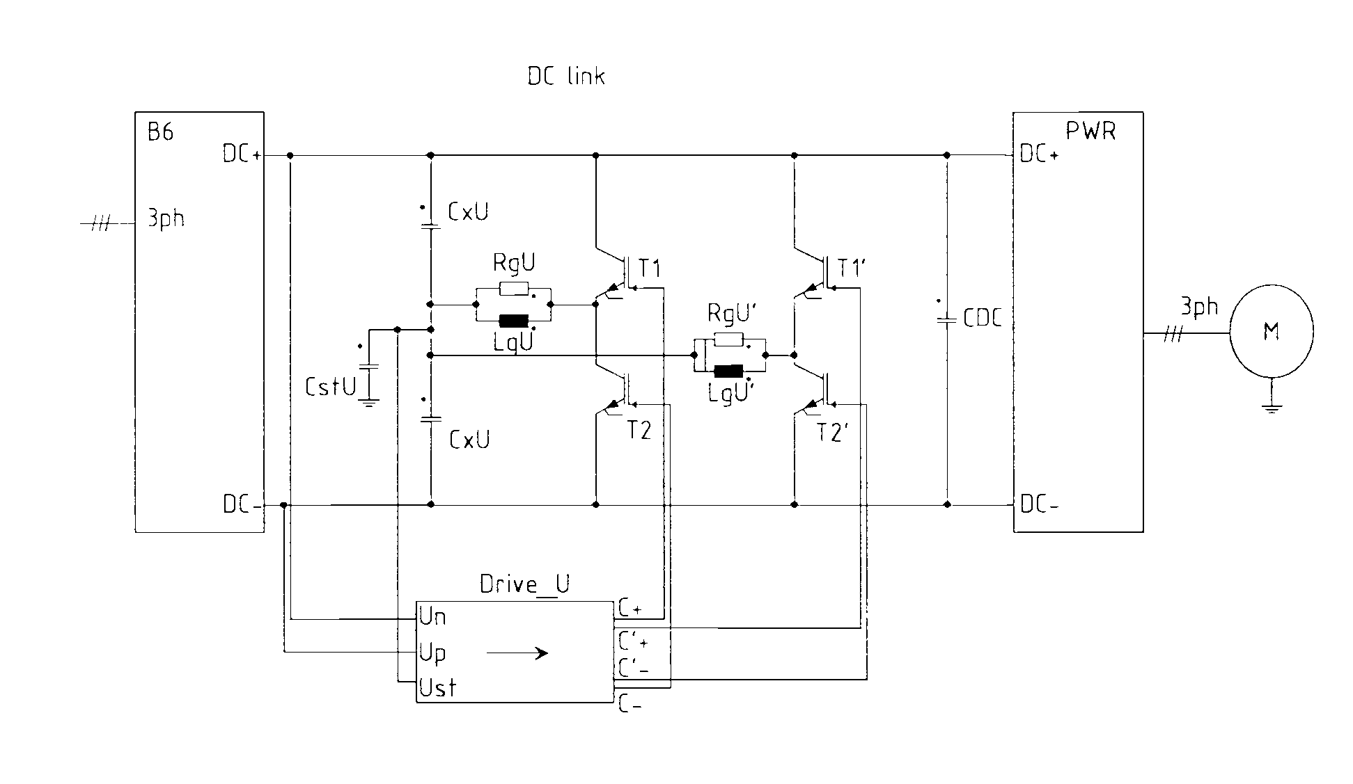
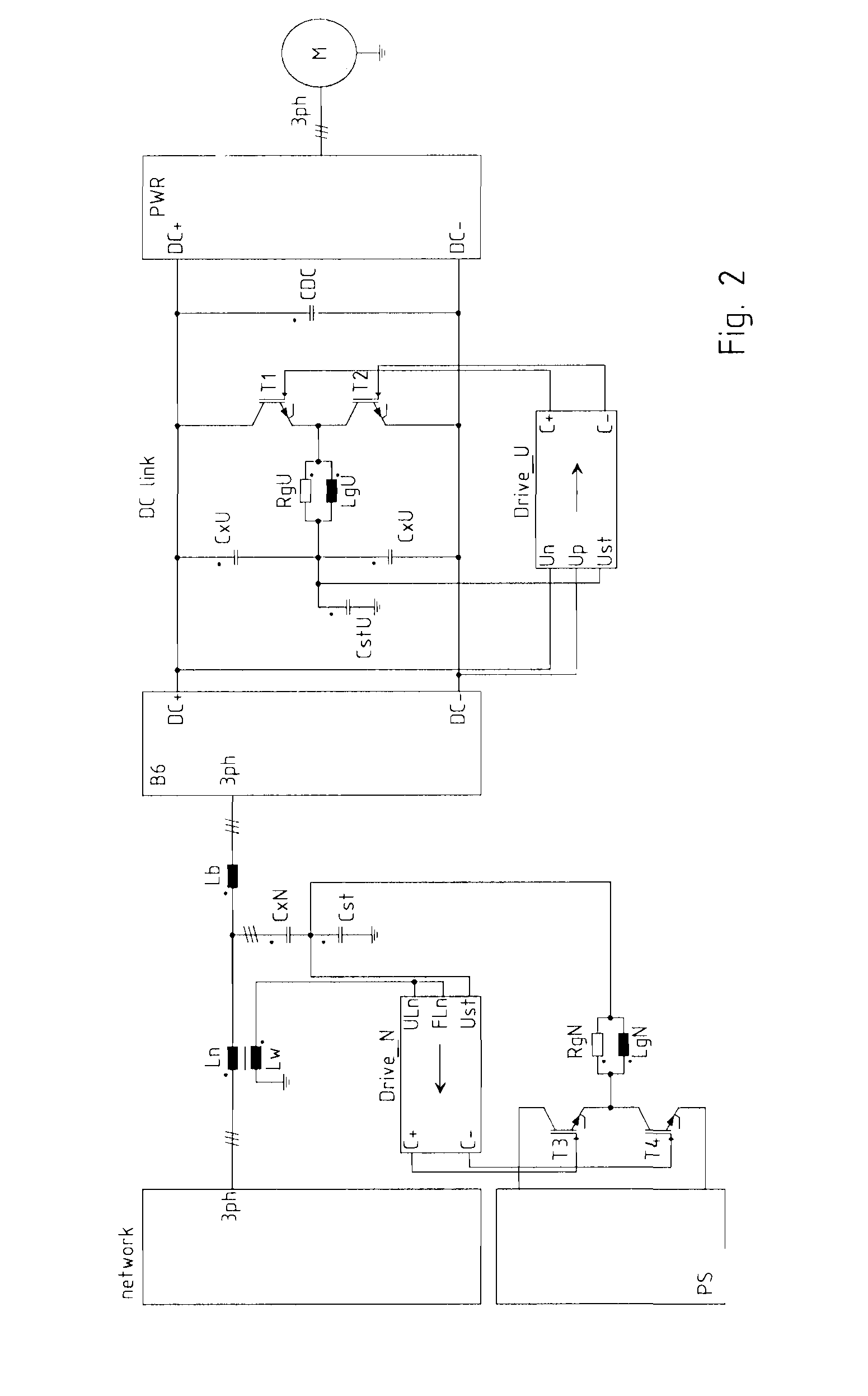
[0020]FIG. 2 shows an embodiment of an EMC management system as shown in FIG. 1. A first active EMC filter is arranged between the AC network and the rectifying bridge B6 in the AC link and a second active EMC filter is arranged between the rectifying bridge B6 and the switched bridge PWR of the inverter in the DC link. FIG. 2 represents the AC link in unifilar fashion, and therefore only one representative phase of the three phases of the AC link is shown.

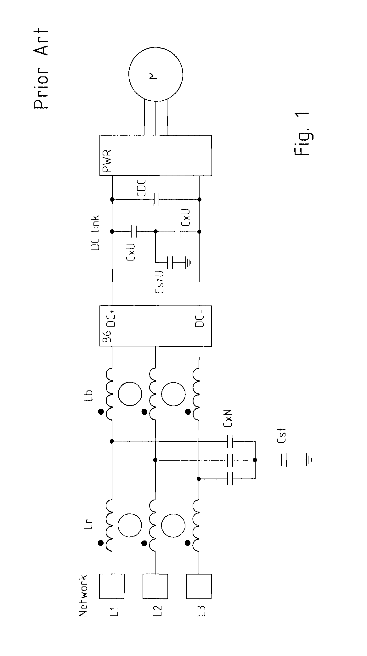
[0021]The first active EMC filter comprises as passive filter elements as already described in FIG. 1 two filter chokes Ln and Lb in each phase, an ‘X’-capacitor C×N connected between each phase (here three) and a star point and a filter capacitor Cst connected between the star point and ground. Thus, the passive filter part of the first active EMC filter in the AC-link has a LCL structure.

[0022]In this example, chokes Ln and Lb are three-phase current-compensated chokes. The filter choke Ln must carry the same load current as the...


PUM


Abstract

Active EMC filter connectable between an electric power source and an electric load, comprising: capacitors (C×N, C×U) connected between active conductors of said power source and a star point electric node; a filter capacitor (Cst, CstU) connected between said star point and ground;a half-bridge comprising two switching devices (T3, T4; T1, T2) connected in cascade between a positive supply voltage and a negative supply voltage; a smoothing circuit (RgN, LgN; RgU, RgU) connected between a common node of said switching devices and said star point; and a control unit (Drive_N, Drive_U) driving said switching devices (T3, T4; T1, T2) digitally either in an ON-state or in an OFF-state, such as to limit a leakage current.

Description

REFERENCE[0001]The present application claims convention priority of the Swiss patent application CH13 / 0798 which is hereby incorporated by reference.FIELD OF THE INVENTION[0002]The present invention concerns an electromagnetic compatibility (EMC) filter, whose aim is the attenuation or the suppression of electromagnetic disturbances generated by electric devices, which could otherwise affect other devices in proximity or connected to the same power line.[0003]More specifically, an embodiment concerns an EMC mitigation system for an electric motor connected to a power line through a rectifier and a variable inverter, but the invention is not limited to this specific application. The EMC filter can also be called Active Residual Current Compensator.DESCRIPTION OF RELATED ART[0004]It is currently known in the art to use filters on power lines for the mitigation of electromagnetic noise generated by the switching frequencies generated by modern electrical equipment during use. Typicall...

Claims


Application Information

Patent Timeline
Patent Type & Authority Applications(United States)
IPC IPC(8): H03H11/04
CPCH03H11/04H02M1/12H02M1/44H02M1/123
Inventor HOENE, ECKARTDOMURAT-LINDE, ANDREZEITER, OLEG
Owner SCHAFFNER EMV AG
Why Eureka
Try Eureka