Photonic Bandgap Structures for Multispectral Imaging Devices

a multi-spectral imaging and band gap technology, applied in the field of imaging, can solve the problems of high cost of optical filters, inability to meet the needs of high-quality optical filters in the market, and inability to meet the needs of high-quality optical filters, etc., to achieve enhanced phase separation, enhanced phase separation, and high polymerization

Inactive Publication Date: 2014-10-23
THE RES FOUND OF STATE UNIV OF NEW YORK
View PDF8 Cites 9 Cited by
  • Summary
  • Abstract
  • Description
  • Claims
  • Application Information

AI Technical Summary

Benefits of technology

[0017]In another embodiment, a post-exposure UV curing procedure fully develops the structure and enhances a phase separation between the polymer and the solvent. Upon opening the sandwiched sample, the solvent evaporates and a periodic refractive index modulation is created in the mixture.
[0018]In one embodiment, a photosensitive pre-polymer syrup—a mixture of monomer, photoinitiator, co-initiator, liquid crystal, reactive solvents, and non-reactive solvents—is prepared and sandwiched between two glass slides. This embodiment uses a holographic photo-patterning that combines the techniques of holography and laser induced polymerization in which the pre-polymer syrup is exposed to the spatial interference pattern introduced by multiple coherent laser beams. Photo-polymerization will therefore lead to higher polymerization in the high intensity regions of the interference pattern. In another embodiment, a post-exposure UV curing procedure fully develops the structure and enhances a phase separation between the polymer and the solvent. Upon opening the sandwiched sample, the solvent evaporates and a periodic refractive index modulation is created in the mixture.
[0022]In another embodiment, a one-step fabrication method to realize a novel graded, periodic holographic photopolymer reflection grating is presented. The period of the reflector at different position along the structure is varied gradually, leading to a rainbow-colored reflection image in the same viewing angle. Compared to previously reported graded photonic or plasmonic structures prepared by expensive focus ion beam (FIB) milling or electron beam lithography techniques, this holographic photo-patterning method is low-cost for large area fabrication. For example, the invention provides graded holographic photopolymer reflection grating filters which can be used in an ultra-compact multispectral imager. The invention can be integrated with portable electronics including cell phones, web-cameras, and laptops. The grating filters, when used in combination with an imaging device can be used for multiple purposes, including diagnostics and anti-counterfeiting with a high degree of accuracy at a low cost.

Problems solved by technology

But, for these high-end and high-definition applications, high quality optical filters and cameras are required, leading to the expensive cost for the commercial products.
To date, there are no low-cost, high-quality optical filter for products in the market that can perform simple multispectral and hyperspectral imaging.
Needless to say, these optical filters are expensive and susceptible to physical forces that might alter the thickness of each layer (such as pressure, temperature, or mechanical stress).
For example, graded photonic or plasmonic structures have been prepared by expensive focus ion beam milling or electron beam lithography techniques.
However, the prior art structures and the structures by Hsaio et al. cannot be made multispectral at the same viewing angle.
Therefore, the previous attempts and the prior art have been unsuccessful at developing an easily manufacturable, durable, and precise photonic bandgap capable of multispectral reflection at a single viewing angle.

Method used


Image

  • Photonic Bandgap Structures for Multispectral Imaging Devices
  • Photonic Bandgap Structures for Multispectral Imaging Devices
  • Photonic Bandgap Structures for Multispectral Imaging Devices

Examples


Embodiment Construction

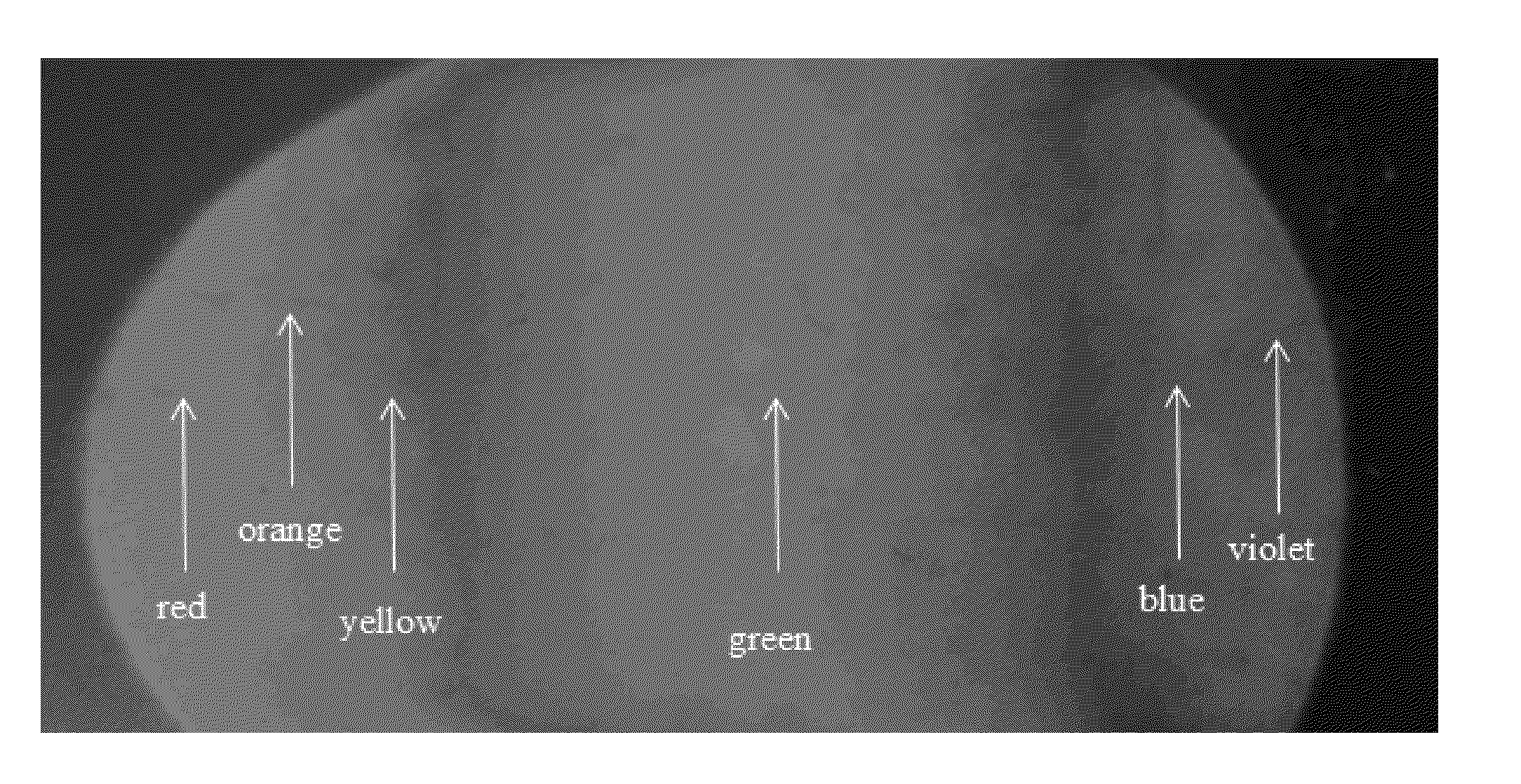
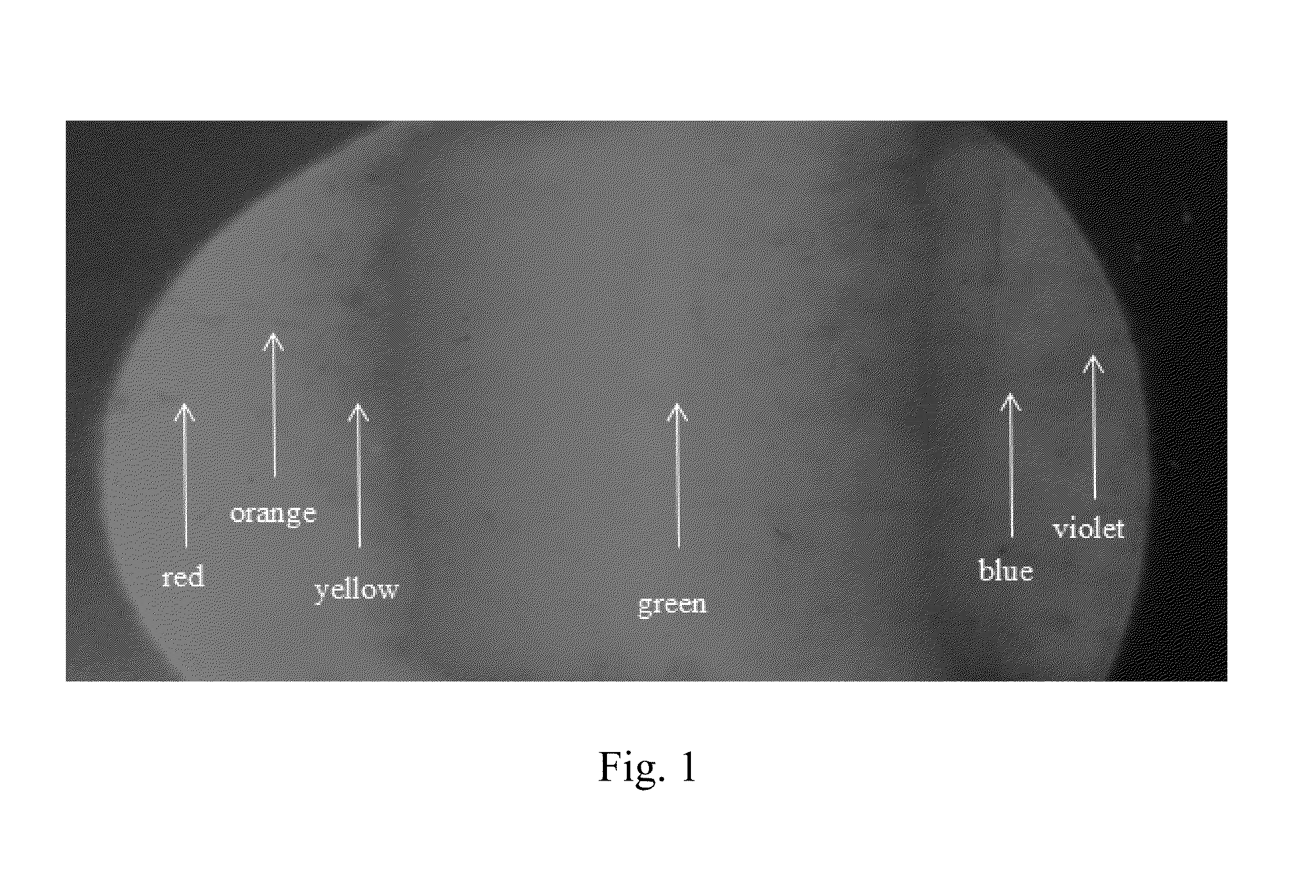
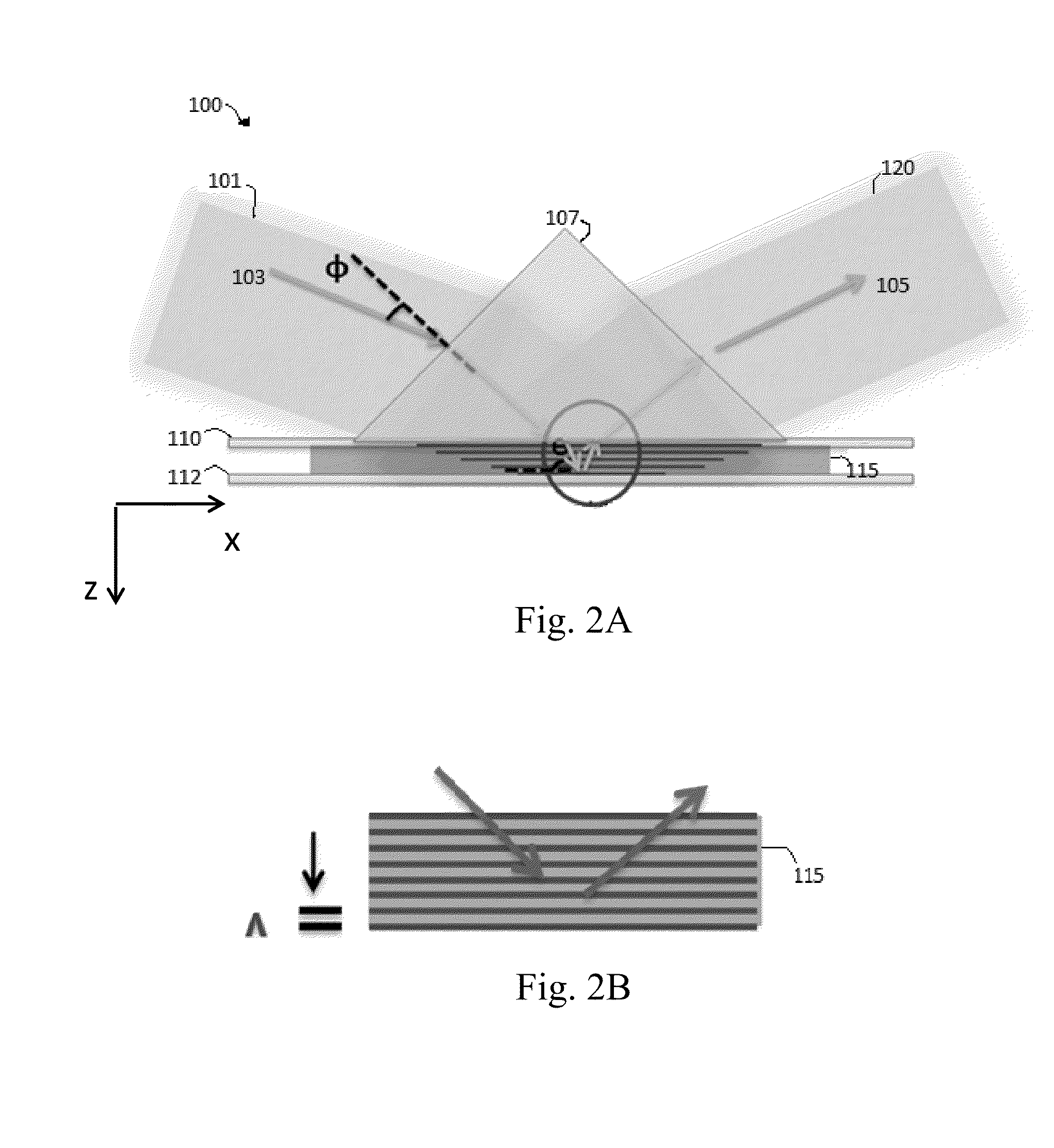
[0050]The present invention may be described as a method of making a photonic bandgap structure. FIG. 4 illustrates two such methods. Generally, photonic bandgap structures can be described as optical nanostructures that manipulate the propagation of photons. The photonic bandgap structures herein may contain periodic, regularly repeating internal regions of high and low refractive indices. The areas of high and low refractive indices are created due to polymerization caused by exposure to a spatial interference pattern created by passing a collimated laser beam through a lens or prism. This refractive index modulation changes the transmission / reflection of light in such a way that prevents certain wavelengths of light from propagating through the structure. Photonic bandgap structures are attractive optical materials for controlling and manipulating the flow of light and can be employed in thin film optics ranging from low or high reflection coatings on lenses, mirrors and optical ...


PUM


Abstract

The invention discloses methods for making photonic bandgap structures and photonic bandgap structures made by those processes. In one embodiment, the photonic bandgap structure is flexible. In another photonic bandgap structure, the structure has a graded, periodic grating. One embodiment of a method according to the present invention comprises the steps of preparing a pre-polymer mixture, positioning that mixture between two slides, exposing the mixture to electromagnetic radiation, curing the mixture, and discarding at least one of the slides. In another embodiment of the method, the pre-polymer mixture is exposed to the electromagnetic radiation through a prism. In one embodiment of the method, the pre-polymer mixture is exposed to the electromagnetic radiation through a lens.In one embodiment of the invention, the photonic bandgap structure is used as a filter in a multispectral imaging device comprising a imaging device, the filter, a processor, and an electronic image storage device.

Description

CROSS-REFERENCE TO RELATED APPLICATION[0001]This application claims the benefit of priority to U.S. provisional patent application Ser. No. 61 / 555,631, filed on Nov. 4, 2011.FIELD OF THE INVENTION[0002]This invention relates generally to the field of imaging and more particularly to multispectral imaging based on photopolymer reflection grating filters.BACKGROUND OF THE INVENTION[0003]Multispectral imaging and hyperspectral imaging are widely used in remote sensing for military and defense applications, bio-imaging, as well as environmental, agricultural and climate monitoring. Hyperspectral imaging is part of a class of techniques commonly referred to as spectral imaging or spectral analysis. Hyperspectral imaging is related to multispectral imaging. The distinction between hyper- and multi-spectral is sometimes based on an arbitrary “number of bands” or on the type of measurement, depending on what is appropriate to the purpose.[0004]Multispectral imaging deals with several images...

Claims


Application Information

Patent Timeline
Patent Type & Authority Applications(United States)
IPC IPC(8): G02B1/00H04N5/33H04N5/232G02B5/18
CPCG02B1/005H04N5/23238H04N5/332G02B5/1857G02B6/02133G02B6/1225G01J3/0256G01J3/18G01J3/32G01J2003/1213B82Y20/00G02B6/138H04N23/11H04N23/698
Inventor GAN, QIAOQIANGCARTWRIGHT, ALEXANDER N.LIU, KEXU, HUINA
Owner THE RES FOUND OF STATE UNIV OF NEW YORK
Why Eureka
Try Eureka