Process and catalyst for the hydrotreatment of a heavy hydrocarbon feedstock

Active Publication Date: 2014-10-23
SHELL USA INC
View PDF1 Cites 16 Cited by
  • Summary
  • Abstract
  • Description
  • Claims
  • Application Information

AI Technical Summary

Benefits of technology

[0015]In one aspect, the invention encompasses a method of making a catalyst composition useful in the hydrotreatment of a heavy hydrocarbon feedstock. In very broad terms, this method comprises the steps of providing an alumina support particle comprising gamma alumina, said support having a median pore diameter in the range of from 100 Å to 120 Å, a surface area in the range of from 290 m2/g to 235 m2/g, and a total mercury pore volume less than 0.85 cc/g; and contacting the alumina support particle with a catalytic solution where the solution comprises a Group 6 metal component and a Group 10 metal component to thereby provide an impregnated alumina support which serves as a catalyst composition.
[0016]In another aspect, the invention encompasses a method of making a catalyst composition useful in the hydrotreatment of a heavy hydrocarbon feedstock. This method comprises the steps of forming a shaped support particle comprising pseudo-boehmite powder; heat treating the shaped support particle at a temperature between 676° C. and 788° C. to achieve a heat treated support particle having a median pore diameter in the range of from 100 Å to 120 Å and a total mercury pore volume less than 0.85 cc/g; and contacting the alumina support particle with a catalytic solution where the catalytic solution comprises a Group 6 metal component and a Group 10 metal component to thereby provide an impregnated alumina support. The impregnated alumina

Problems solved by technology

The hydrotreatment of heavy hydrocarbon feedstock is particularly difficult because such feeds tend to have high concentrations of contaminating sulfur and nitrogen compounds and may require the use of more severe process conditions than those needed t

Method used


Image

  • Process and catalyst for the hydrotreatment of a heavy hydrocarbon feedstock
  • Process and catalyst for the hydrotreatment of a heavy hydrocarbon feedstock
  • Process and catalyst for the hydrotreatment of a heavy hydrocarbon feedstock

Examples


example 1

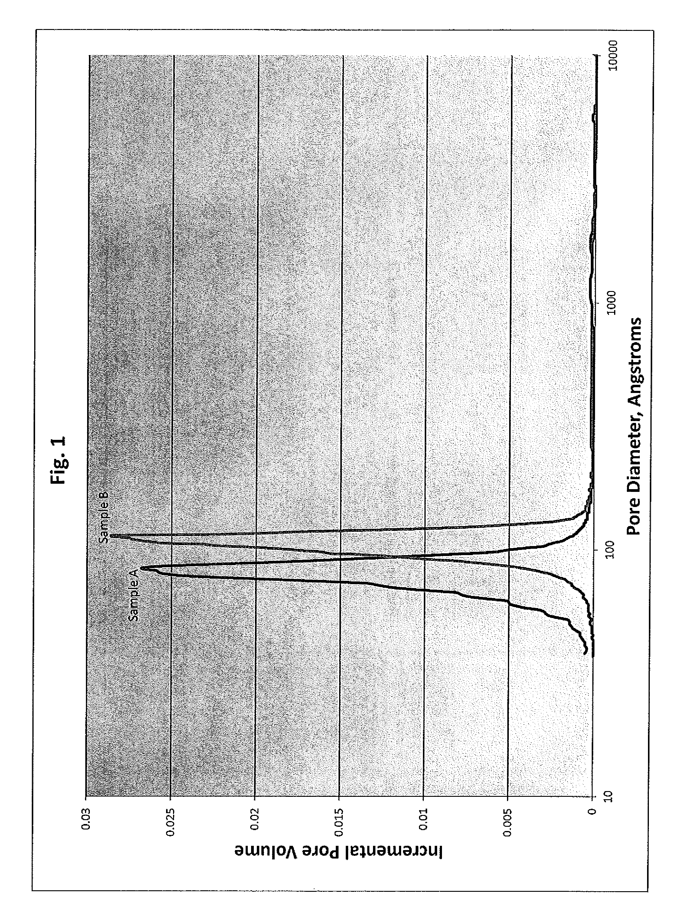
[0087]Example 1 describes the preparation of the shaped alumina support particle used in the making of the final catalyst composition of the invention. The shaped alumina support particle was heat treated (calcined) at various temperatures to determine the effect that temperature has on the properties of the heat treated support used to make the final catalyst composition of the invention and upon the catalytic performance of the final catalyst composition of the invention.

[0088]The shaped support was prepared by mixing 3285 grams of pseudo-boehmite alumina powder with a loss on ignition (LOI) of 23.9% with 3418 g of water and 54 grams of nitric acid (69.4%) using a muller mixer. The components were mixed for a sufficient period of time to provide an extrudable paste. The resulting paste was extruded through 1.3 mm extrusion dies to form extrusion particles of the shaped support. The particles were dried in air at 127° C. for four hours to give the dried extrusion particles.

[0089]A ...

example 2

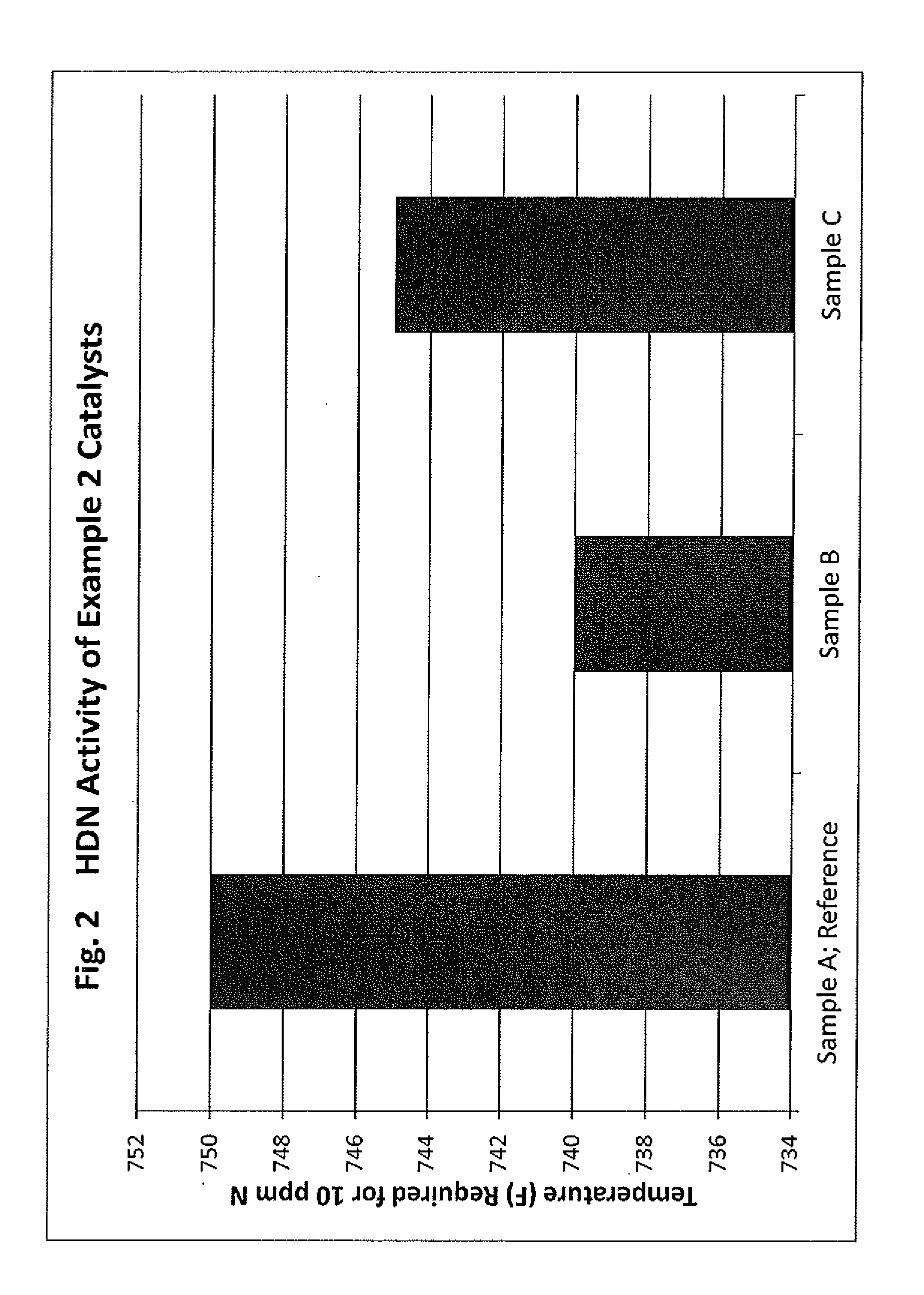
[0094]This example describes the preparation of catalyst compositions using the heat treated (calcined) samples described in Example 1. These catalyst compositions were used in the hydrotreating activity tests of Examples 3-4.

[0095]The catalyst compositions were prepared by impregnating the samples of Example 1 with a catalytic impregnation solution comprising a Group 6 metal component and a Group 10 metal component to thereby provide an impregnated alumina support. More specifically, the catalytic compositions were prepared by impregnating the samples of Example 1 with a catalytic impregnation solution followed by drying the impregnated samples and calcination of the dried impregnated samples. The impregnation solution was prepared by combining within a container vessel 33.1 grams of molybdenum trioxide (MoO3), 10.4 grams of nickel carbonate (NiCO3), 11.9 grams of 86% concentration phosphoric acid (H3PO4) and 100 grams of deionized water. The mixture was heated to 93° C. (200° F.) ...

example 3

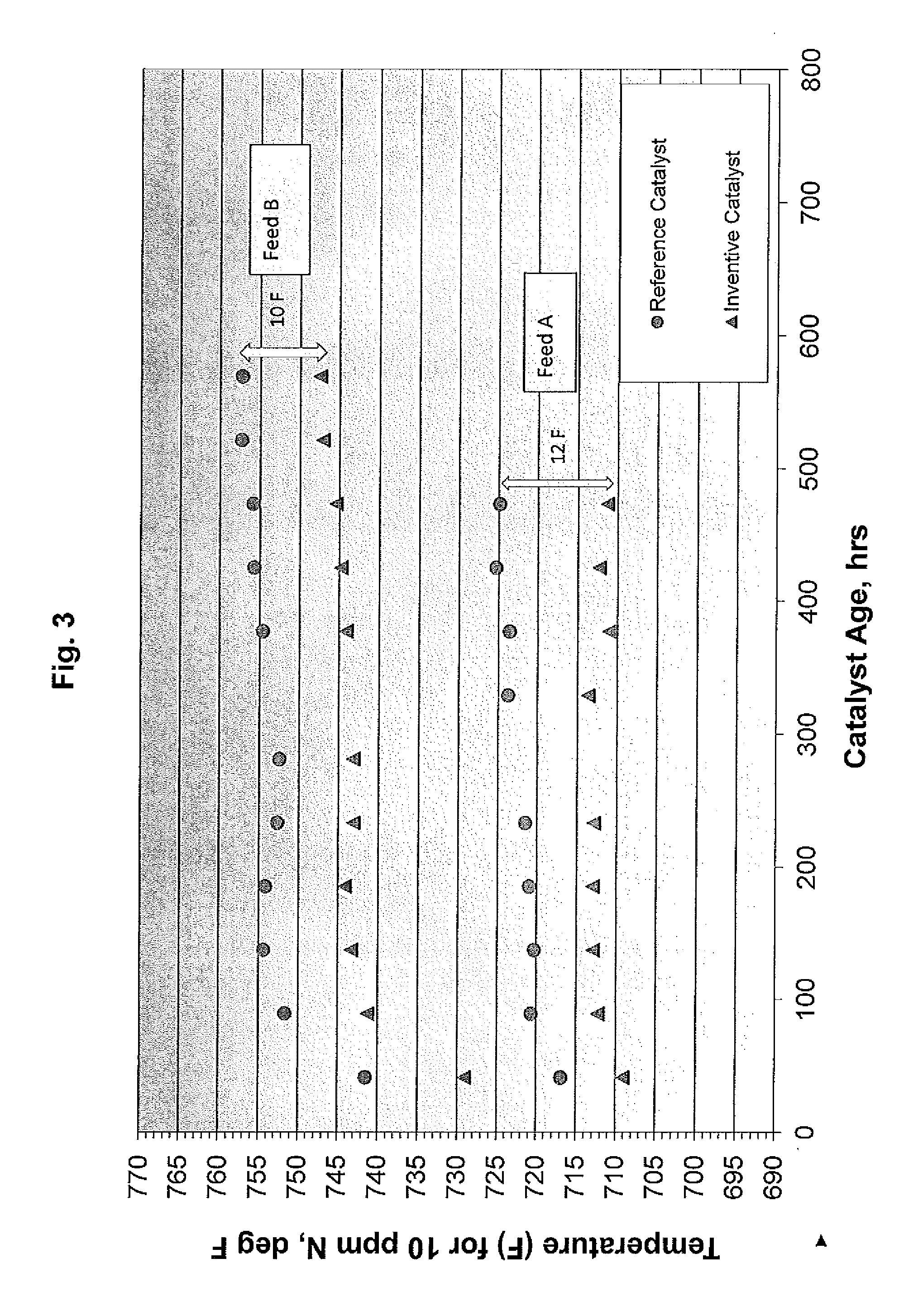
[0097]Example 3 describes the experimental procedure used to measure the performance of catalyst compositions prepared as described in Examples 1 and 2 in the hydrotreating of a heavy vacuum gas oil (HVGO) used in hydrocracking. A laboratory stainless steel isothermal tube reactor was packed with 20 cc of the relevant catalyst and 51 cc of 70 mesh silicon carbide diluent. The catalyst was sulphided using a 5% H2S in H2 gas using a gas rate of 20 liters / hr.

[0098]The temperature was ramped from ambient to 204° C. (400° F.) at 10° C. / hr (50° F. / hr), held for 2 hours, ramped to 316° C. (600° F.) at the same rate, held for 2 hours, and then to 371° C. (700° F.) at the same rate and held for 1 hour. The temperature was then lowered to 93° C. (200° F.) and the test feed introduced under test conditions of 1700 psig outlet pressure (100% H2), 5500 standard cubic feet per barrel (SCFB) hydrogen rate and a liquid hourly space velocity (LHSV) of 1.5 hr-1.

[0099]The temperature was then ramped t...


PUM

PropertyMeasurementUnit
Temperatureaaaaaaaaaa
Fractionaaaaaaaaaa

Abstract

A method of hydrotreating a heavy hydrocarbon feedstock using a hydrotreating catalyst having specific properties that make it effective in removing nitrogen and sulfur from the feedstock is disclosed. The catalyst is composed of an alumina support particle having a specific pore diameter distribution which is achieved in part, by the use of pseudo-boehmite as the alumina source and specific calcining temperatures. The hydrotreatment catalyst also comprises a Group 6 metal component (e.g., molybdenum) and a Group 10 metal component (e.g., nickel), and optionally, a phosphorus metal component, which are supported by the alumina support particle.

Description

[0001]This non-provisional application claims priority from U.S. Provisional Application Ser. No. 61 / 812,932 filed Apr. 17, 2013, which is hereby incorporated by reference in its entirety.BACKGROUND OF THE INVENTION[0002]This invention relates to a process and a catalyst composition used in the process for the hydrotreatment of a heavy hydrocarbon feedstock. This invention also relates to a catalyst and process for the manufacture of a hydrocarbon product having a low concentration of nitrogen and sulfur. The invention further relates to a high activity hydrodesulfurization and hydrodenitrogenation catalyst, a method of making such high activity catalyst, and a process for hydrotreating a heavy hydrocarbon feedstock using the high activity hydrodesulfurization and hydrodenitrogenation catalyst.[0003]The catalytic hydrotreatment of hydrocarbon feedstock to remove impurities such as sulfur, nitrogen, and metal compounds is a commonly used process to improve or upgrade such hydrocarbon...

Claims


Application Information

Patent Timeline
IPC IPC(8): B01J23/883B01J21/04
CPCB01J21/04B01J23/883B01J37/08B01J23/85B01J27/199B01J35/002B01J35/026B01J35/1019B01J35/1042B01J35/1061B01J37/0009B01J37/0207C10G45/08
Inventor SMEGAL, JOHN ANTHONY
Owner SHELL USA INC
Why Eureka
Try Eureka