Radio frequency power source having precise power detector

Active Publication Date: 2014-11-13
INST OF MICROELECTRONICS CHINESE ACAD OF SCI
View PDF6 Cites 2 Cited by
  • Summary
  • Abstract
  • Description
  • Claims
  • Application Information

AI Technical Summary

Benefits of technology

The present invention provides a RF power source with a precise power detector that can detect RF power accurately and with a wide range, consistency, and small dead-band. Compared to previous solutions, the present invention uses a precise detecting module and a multi-way switch, which simplifies components and reduces cost. Additionally, the use of low break-over voltage Schottky diodes and a high-speed operational amplifier ensures distortionless detection of RF signals commonly used in semiconductor process equipment.

Problems solved by technology

It is impossible for an existing RF power detector to achieve the consistency of the accuracy of the RF power detection since the detecting circuit of the existing RF power detector has a big dead-band, and a small dynamic range.
That is to say, since there are large errors during the detection of small RF power, it is uncertain whether the process equipment can process a wafer with a smaller linewidth.
As to the 32 nm manufacturing process, if the existing technology is used, it is impossible to achieve a thin linewidth, and thus an expected pattern, this finally results a failure of the manufacturing process.

Method used


Image

  • Radio frequency power source having precise power detector
  • Radio frequency power source having precise power detector
  • Radio frequency power source having precise power detector

Examples


first embodiment

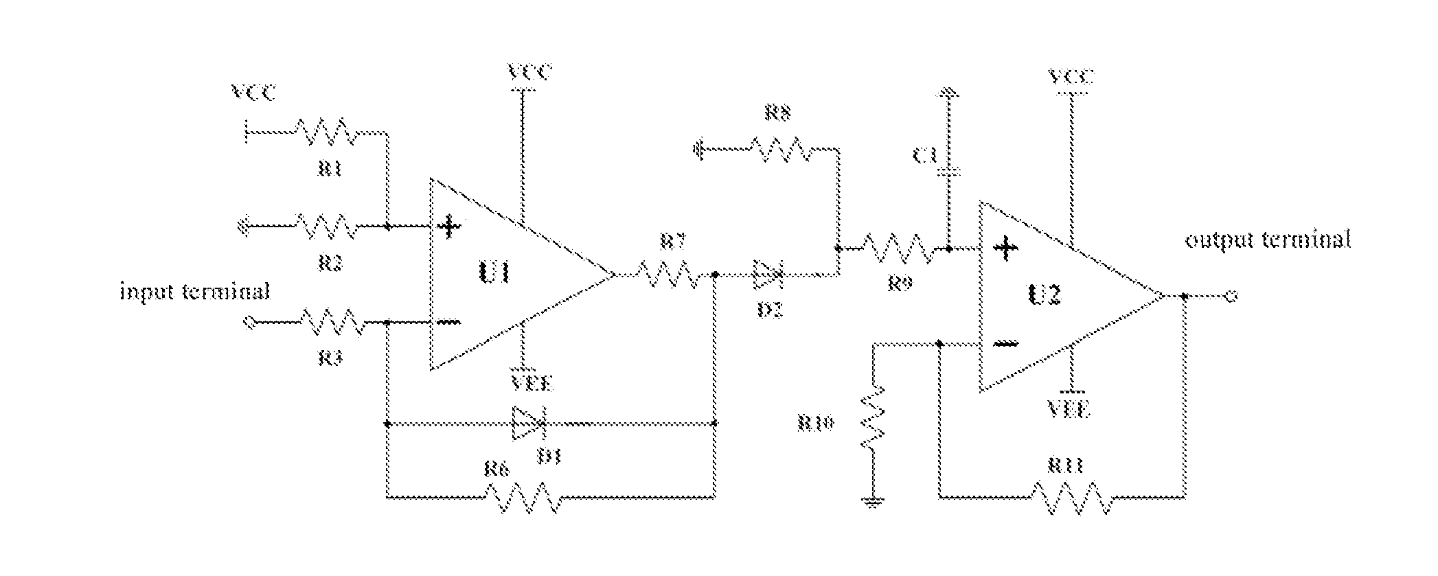
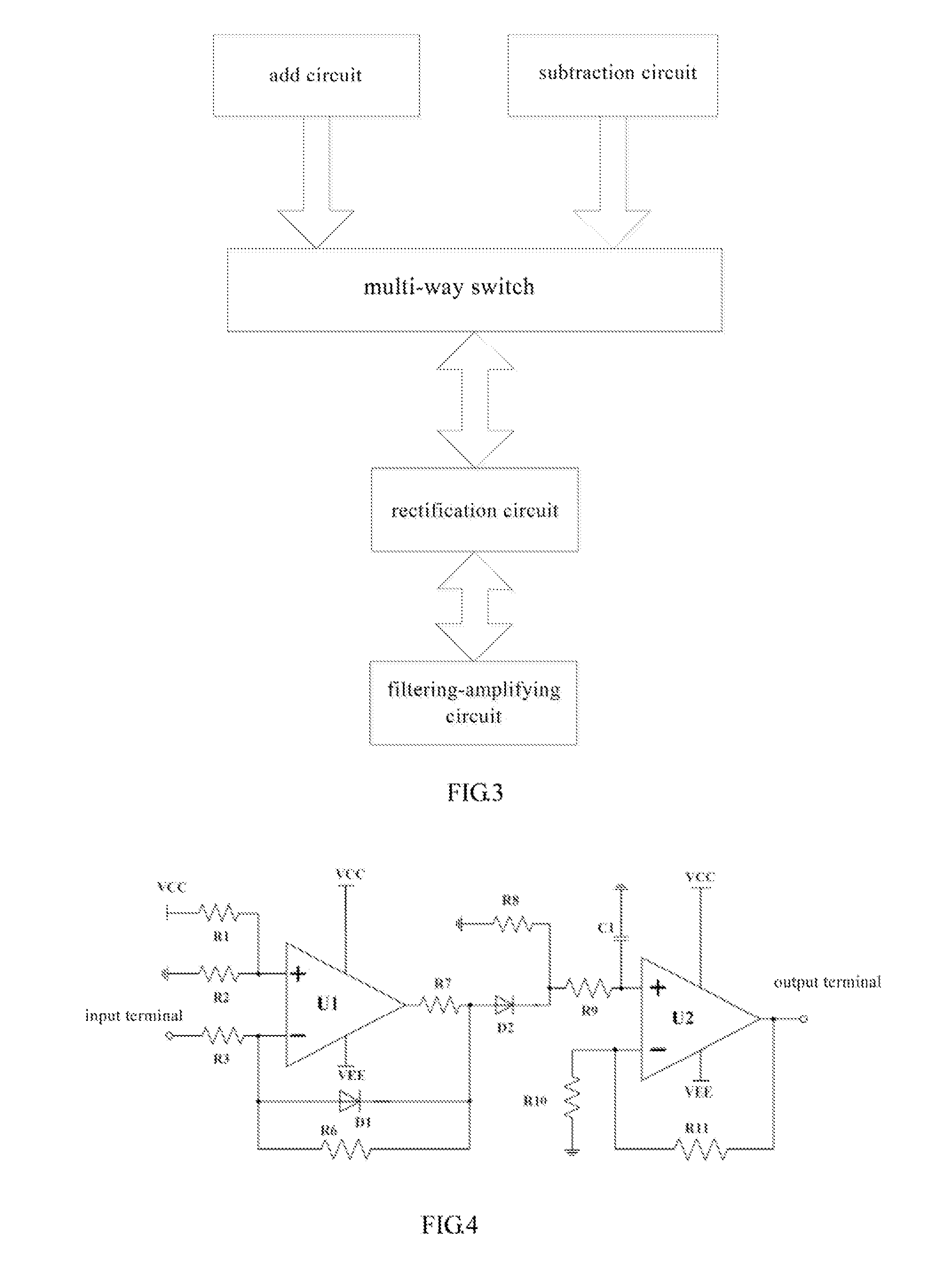
[0031]It is shown in FIG. 4 that a rectification circuit and a filtering-amplifying circuit of the precise detecting module of the present invention. The rectification circuit mainly comprises a rectifying operational amplifier U1 and detecting diodes D1, D2. An anode of the detecting diode D1 is connected to an inverting input terminal of the rectifying operational amplifier U1, and a cathode of the detecting diode D1 is connected to an output terminal of the rectifying operational amplifier U1. The detecting diode D2 is disposed between the output terminal of the rectifying operational amplifier U1 and an input terminal of the filtering-amplifying circuit.

[0032]The detecting diodes D1, D2 may be Schottky diodes with low break-over voltage, preferably IN5711 model diodes. The rectifying operational amplifier is a high-speed operational amplifier with a bandwidth greater than 1 GHz, preferably a high-speed operational amplifier OPA657 with 1.6 GHz bandwidth made of Texas Instruments...

second embodiment

[0036]It is shown in FIG. 5 that the rectification circuit and the filtering-amplifying circuit of the precise detecting module of the present invention. By comparing with the embodiment shown in FIG. 4, the embodiment shown in FIG. 5 only has modifications with respect to the input resistors of the rectification circuit. Instead of using one input resistor R3, the embodiment shown in FIG. 5 uses resistors R3, R4, and R5 to form a T-shape network. This solution can achieve the division of current and voltage during the input of large signals, reduce the power consumption on the resistors, protect the rectifying operational amplifier, and thus enlarge the input range of the precise detecting module (i.e., the embodiment shown in FIG. 4 cannot detect RF signals with large power, hut the embodiment shown in FIG. 5 can do it). The resistances of these resistors may be determined according to the gain and the input range of the precise detecting module.

third embodiment

[0037]It is shown in FIG. 6 that the rectification circuit and the filtering-amplifying circuit of the precise detecting module of the present invention. By comparing with the embodiment shown in FIG. 5, the embodiment shown in FIG. 6 uses a second-order filtering-amplifying circuit instead of the first-order filtering-amplifying circuit. This manner is beneficial in filtering more harmonic waves so as to ensure the analog-digital converter within the microcontroller to obtain more accurate numerical values (i.e., the numerical values represent the incident power and the reflected power) for further operational processes of the microprocessor.


PUM


Abstract

A radio frequency (RF) power source having a precise power detector includes a RF signal generator, a RF power amplifying circuit, a power supply circuit, and a precise power detector. The precise power detector includes a voltage mutual inductor, a current mutual inductor, a precise detecting module, and a microcontroller integrated with an analog-digital (A / D) converter and a micro-processing unit, wherein the voltage mutual inductor and the current mutual inductor are respectively connected with the precise detecting module. The precise detecting module includes an add circuit, a subtraction circuit, a rectification circuit, and a filtering-amplifying circuit, wherein the add circuit and the subtraction circuit are respectively connected with the rectification circuit, the rectification circuit connects to the filtering-amplifying circuit, the filtering-amplifying circuit connects to the microcontroller integrated with the A / D converter and the micro-processing unit.

Description

TECHNICAL FIELD[0001]The present invention relates to a RF (radio frequency) power supply, in particular to a RF power supply with a precise power detector.BACKGROUND OF THE INVENTION[0002]A RF power supply is a device for generating RF power signals, and is a core component of the semiconductor process equipment. All the equipments that generate plasma for processing material need the RF power supply to provide energy. Process manufacturing equipments of integrated circuits, solar cells and LEDs (Light Emitting Diodes), such as etcher, PVD (Physical Vapor Deposition) equipment, PECVD (Plasma Enhanced Chemical Vapor Deposition) equipment, ALD (Atomic layer deposition) equipment and so on are equipped with the RF power supplies with different power specifications.[0003]A RF power supply is generally be composed of a RF signal generator, a RF power amplifying circuit, power supplying lines and a RF power detector. Currently, the integrated circuit manufacturing industry develops towar...

Claims


Application Information

Patent Timeline
IPC IPC(8): H02M7/06
CPCH02M7/066H01J37/32082H01J37/32174H01J37/32935H03F3/195H03F3/45475H03F2203/45138H03F2203/45518H03F2203/45528G01R27/00H04B17/00G01R31/00
Inventor LI, YONGTAOZHAO, ZHANGYANQIN, WEILI, YINGJIEXIA, YANG
Owner INST OF MICROELECTRONICS CHINESE ACAD OF SCI
Why Eureka
Try Eureka